Cart is empty.
.png)


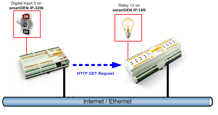
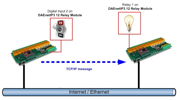
Box to box mode connects inputs and outputs between two different Denkovi Modules without any software between them. DAEnetIP3 and SmartDEN communicates with other Denkovi relay boards using TCP/IP or HTTP GET requests and transfer the commands from input to an output (relay).
How does it work
"Box to box" mode allows direct communication between two devices over a network (internet/ethernet), without any PC or software. We provide several modules which support this mode. Usually this is acheived when the "Input Module" sends some kind of message over the network upon certain event - button pressing, temperature alarm or other event. This message may be TCP/IP or UDP raw message (text), HTTP GET request, SNMP trap and so on. The "Output Module" receives this message and activae it's output (relay). This is so called "distributed" system as well.
Box to box compability map
The "Input Modules" are able to send messages over the network. They are the senders of the messages (in network context they are clients). From the other hand the "Output Modules" are those one which supports outputs (relays) and they can receive the message. They are so called receivers or servers. Bellow is shown the compability table of our box-to-box devices:
| Input Module (Sender/client) | Message Type | Compatible output Module (Receiver/server) | Note |
| smartDEN 32 Input Module | HTTP GET | smartDEN IP-16R-XX (smartDEN IP-16R, smartDEN IP-16R-BOX, smartDEN IP-16R-MQ, smartDEN IP-16R-MQ-BOX, smartDEN IP-16R-MT, smartDEN IP-16R-MT-BOX) | Encrypt Password option in "HTTP/XML/JSON Settings" web page from the output module must be unchecked |
| HTTP GET | smartDEN IP-Watchdog | Encrypt Password option in "HTTP/XML/JSON Settings" web page from the output module must be unchecked | |
| HTTP GET | smartDEN IP-Maxi-XX (smartDEN IP-Maxi, smartDEN IP-Maxi-MQ) | Encrypt Password option in "HTTP/XML/JSON Settings" web page from the output module must be unchecked | |
| HTTP GET | smartDEN IP-PLC | Encrypt Password option in "HTTP/XML/JSON Settings" web page from the output module must be unchecked | |
| HTTP GET | DAEnetIP4 | Encrypt Password option in "HTTP/XML/JSON Settings" web page from the output module must be unchecked | |
| HTTP GET | Ethernet 12 Relay with DAEnetIP4 | Encrypt Password option in "HTTP/XML/JSON Settings" web page from the output module must be unchecked | |
| HTTP GET | Ethernet 5 Relay with DAEnetIP4 (Ethernet 5 Relay Module with DAEnetIP4 - BOX) | Encrypt Password option in "HTTP/XML/JSON Settings" web page from the output module must be unchecked | |
| HTTP GET | DAEnetIP3-Ex (DAEnetIP3-Wx) | ||
| HTTP GET | Ethernet 12 Relay with DAEnetIP3 (WiFi 12 Relay with DAEnetIP3) | ||
| HTTP GET | Ethernet 5 Relay with DAEnetIP3 (WiFi 5 Relay with DAEnetIP3) | ||
| TCP/IP command | Wi-Fi 16 Relay Module | ||
| DAEnetIP3-Ex (DAEnetIP3-Wx) | TCP/IP command | DAEnetIP3-Ex (DAEnetIP3-Wx) | |
| TCP/IP command | Ethernet 12 Relay with DAEnetIP3 (WiFi 12 Relay with DAEnetIP3) | ||
| TCP/IP command | Ethernet 5 Relay with DAEnetIP3 (WiFi 5 Relay with DAEnetIP3) | ||
| Ethernet 12 Relay with DAEnetIP3 (WiFi 12 Relay with DAEnetIP3) | TCP/IP command | DAEnetIP3-Ex (DAEnetIP3-Wx) | |
| TCP/IP command | Ethernet 12 Relay with DAEnetIP3 (WiFi 12 Relay with DAEnetIP3) | ||
| TCP/IP command | Ethernet 5 Relay with DAEnetIP3 (WiFi 5 Relay with DAEnetIP3) | ||
| Ethernet 5 Relay with DAEnetIP3 (WiFi 5 Relay with DAEnetIP3) | TCP/IP command | DAEnetIP3-Ex (DAEnetIP3-Wx) | |
| TCP/IP command | Ethernet 12 Relay with DAEnetIP3 (WiFi 12 Relay with DAEnetIP3) | ||
| TCP/IP command | Ethernet 5 Relay with DAEnetIP3 (WiFi 5 Relay with DAEnetIP3) |
Note: DAEnetIP3 based devices can serve as Input and Output module at the same time. The other devices can serve either as Input either as Output module only.
Configuring the input: smartDEN IP-32IN Module
First we need to set-up the remote IP of the module we want to control. Go to smartDEN IP-32IN web server -> "Remote Services" page -> working with section "Remote Relay Control".

- Enable - this enables sending conrol messages, must be checked;
- Remote Board Type - from this field we can select which board to control;
- Remote Board Address - the IP address (or URL) of the remote board;
- Remote Board Port - the communication port for the remote board as follows:
- smartDEN IP-16R - the HTTP Port (by default it is 80);
- DAEnetIP3 - the HTTP Port (by default it is 80);
- DAEnetIP4 - the HTTP Port (by default it is 80);
- Wi-Fi 16 Relay Module - the TCP Port (by default it is 8899);
- Remote Board Password - the HTTP/WEB password;
- Remote Board Response Timeout - The connection timeout in seconds. Please note that some output modules (receiver/server) have slower response time in some cases for the HTTP GET requests. So a number of 10 seconds usually is good value for that parameter.
Every digital input can be adjusted to control a relay from the remote module when it changes its state. To do that, go to "Digital Inputs" page.
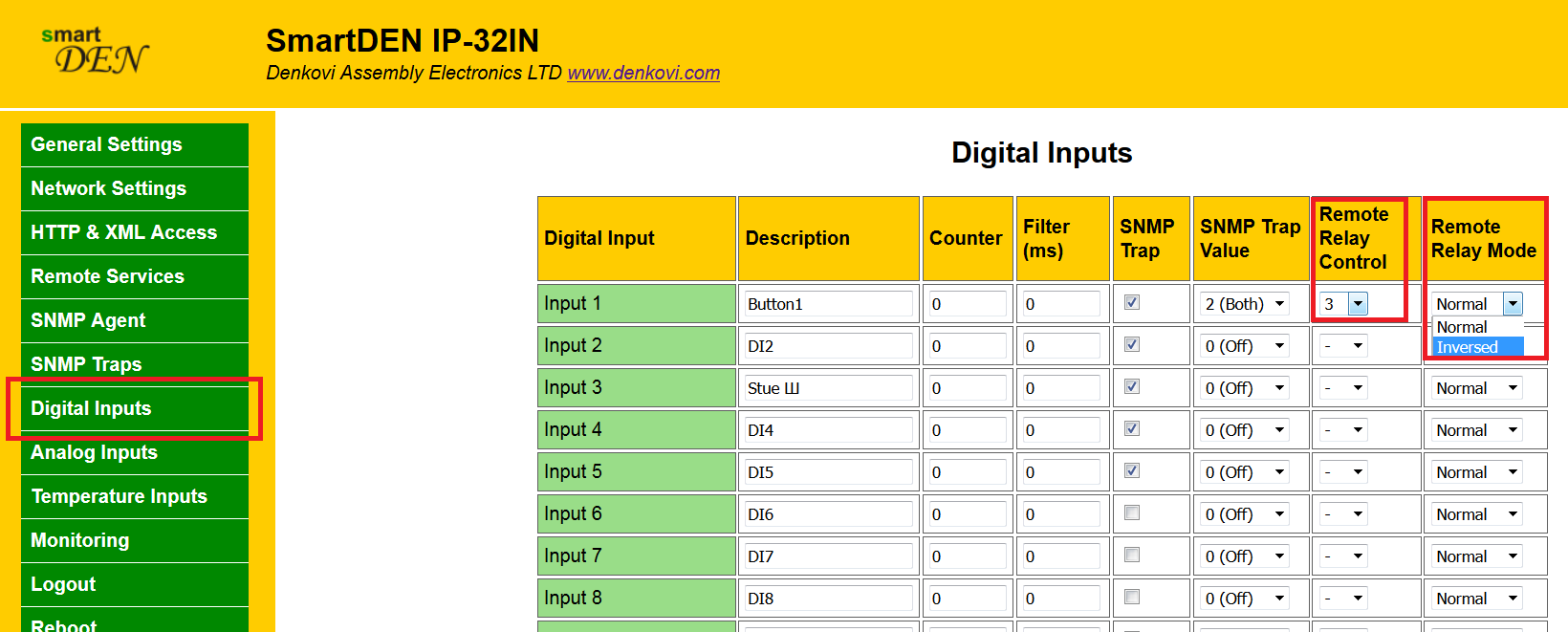
- Remote Relay Control - this parameter select which relay to be controlled up-on digtial input change from the remote relay board. If the selcted value is "-", the remote relay control is disabled;
- Remote Relay Mode - (Normal or Inversed) determines if the relay to be ON or OFF up-on change.
The same is the situation if we want to use the analog inputs when the input level crosses high/low treshold. To do that, go to "Analog Inputs" page.
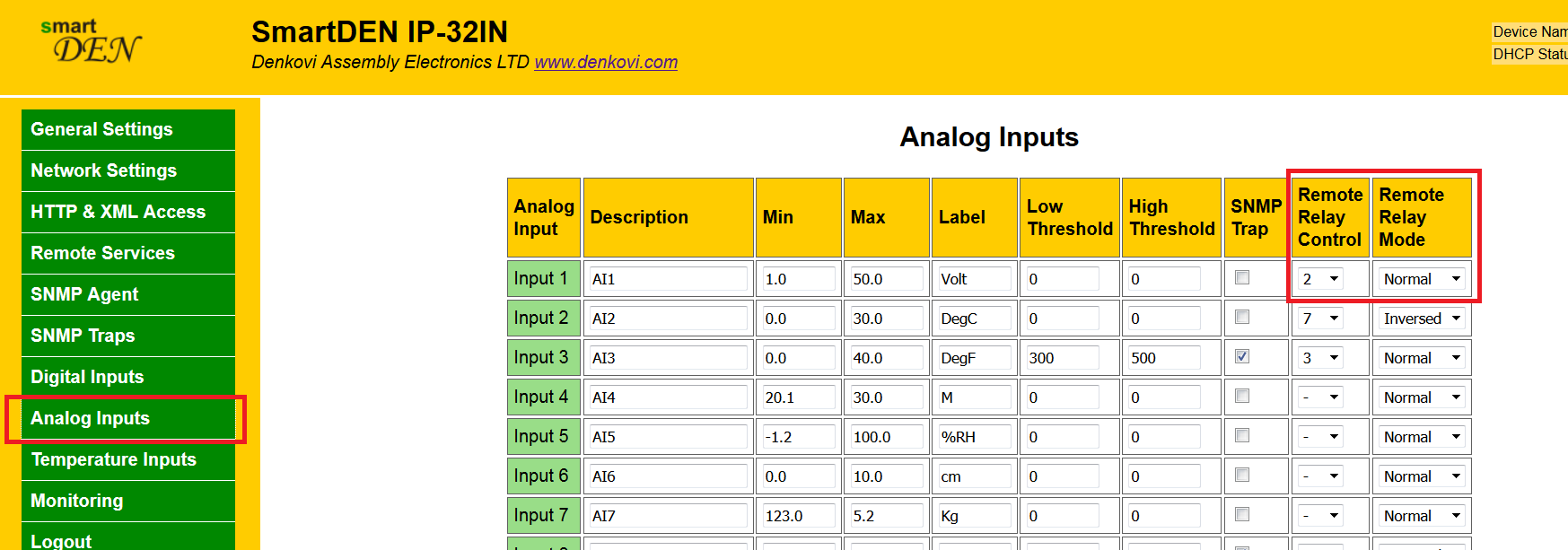
- Remote Relay Control - this parameter select which relay to be controlled up-on analog input treshold crossing from the remote relay board. If the selcted value is "-", the remote relay control is disabled;
- Remote Relay Mode - (Normal or Inversed) determines if the relay to be ON or OFF up-on change.
The temperature inputs also can be used in order to send messages when the temperature crosses high/low treshold. To do that, go to "Temperature Inputs" page.

- Remote Relay Control - this parameter select which relay to be controlled up-on temperature input treshold crossing from the remote relay board. If the selcted value is "-", the remote relay control is disabled;
- Remote Relay Mode - (Normal or Inversed) determines if the relay to be ON or OFF up-on change.
Configuring the input: DAEnetIP3
Here it is the similar story, go to DAEnetIP3 web server -> "Admin Settings" page.

- Remote Server IP - the IP address of the remote board;
- Remote Server Port - the port of the remote DAEnetIP3 board. This port must be the same with the port from the "Local Port range" from the remote DAEnetIP3 board;
- Working Mode - DAEnetIP3-Ex based devices supports only Ethernet interface, so this option is only for the DAEnetIP3-Wx based devices where there is Ethernet and Wireless interface. In that case it must be selcted the network interface used for communication.
The digital inputs (PortB) can control a relay from the remote DAEnetIP3 module when it changes its state. To do that, go to "Digital Inputs" page.

- Mode - the mode must be either "Set output during rising edge" either "Set output during falling edge". The name of the modes indicates how the remote output will be controlled;
- PortA Pin - this is the remote PortA pin (digital output) from DAEnetIP3 board;
- Remote - enables / disables the sending of the TCP/IP control message to the remote board.
The analog inputs (PortC) also can control a output from the remote DAEnetIP3 module when it crosses some threshold. To do that, go to "Analog Inputs" page.
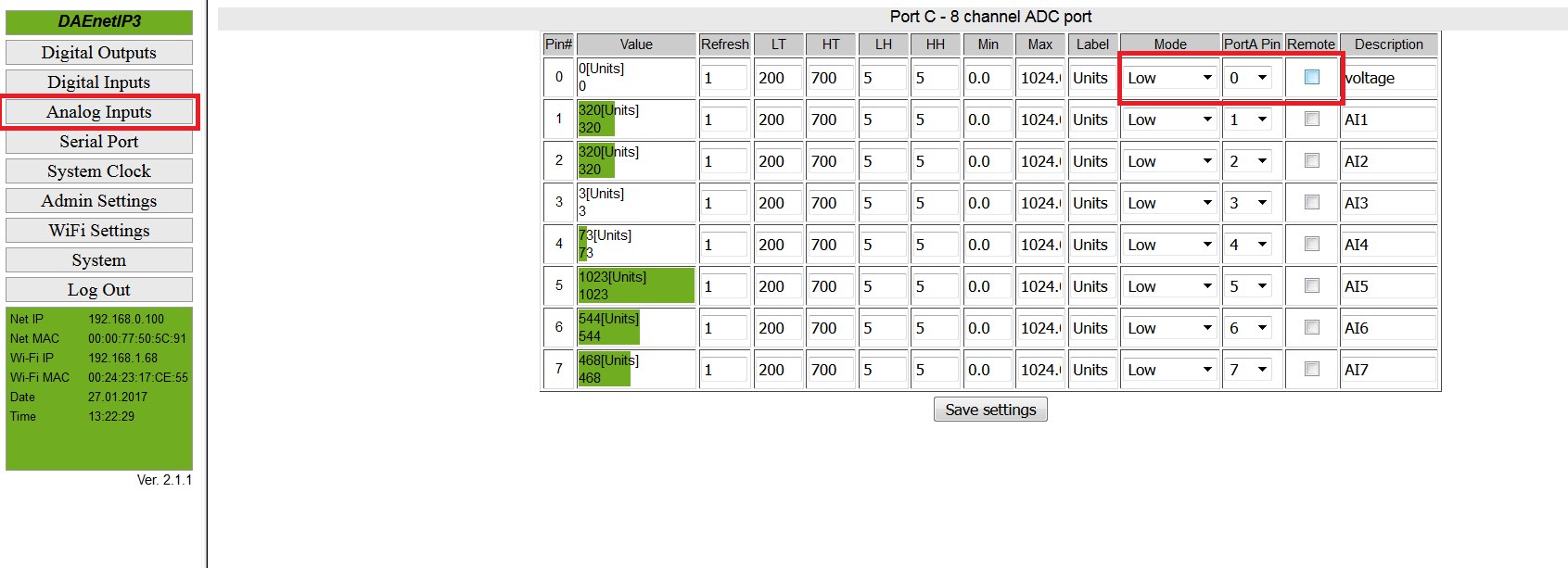
- Mode - the mode must be either "Low","High","Low/High" or "Acc". This mode determines how the command will be send based on the thresholds;
- PortA Pin - this is the remote PortA pin (digital output) from DAEnetIP3 board;
- Remote - enables / disables the sending of the TCP/IP control message to the remote board.
Configuring the output: DAEnetIP4 and smartDEN IP-16R Module (16 Outputs)
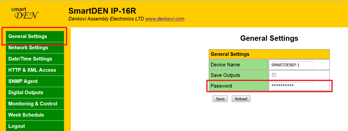
- Password - must mach with the Input Module "Remote Board Password" parameter. Can be set from webserver -> "General Settings" page -> Password;
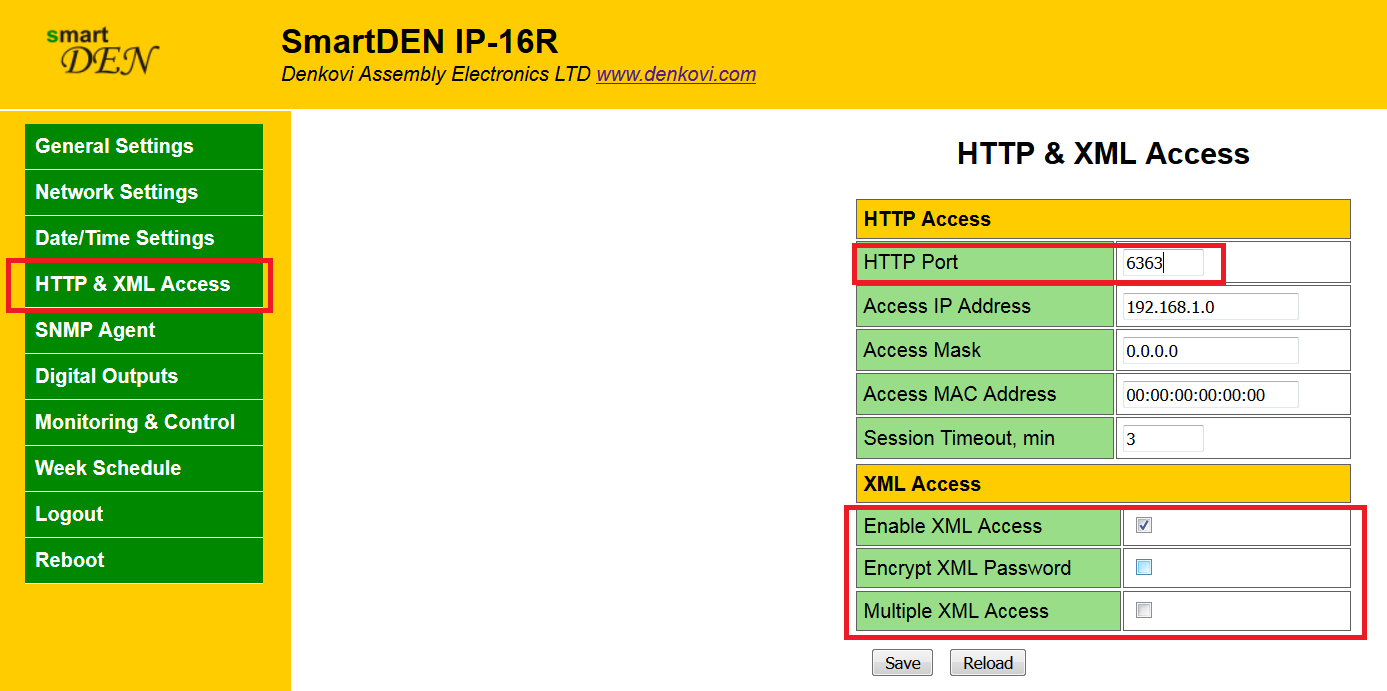
- HTTP Port - must mach with the Input Module "Remote Board Port" parameter. Can be set from webserver -> "HTTP & HML Access" page -> HTTP Port (by default it is 80);
- XML Access - must be set as follows: Enable XML Access - checked, Encrypt XML Password - unchecked, Multiple XML Access - unchecked;
Note: DAEnetIP4 based devices can be set via the same way as their settings are similar to the smartDEN IP-16R Module.
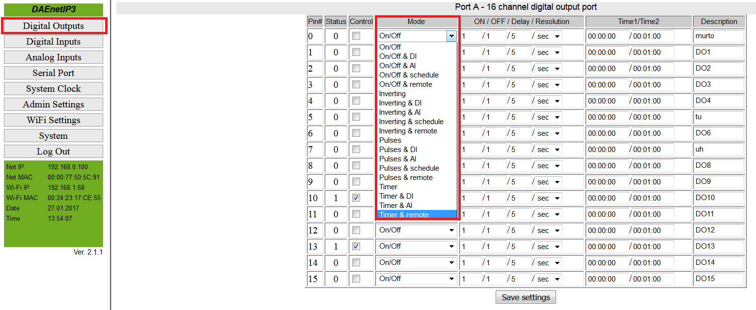
Configuring the output: DAEnetIP3
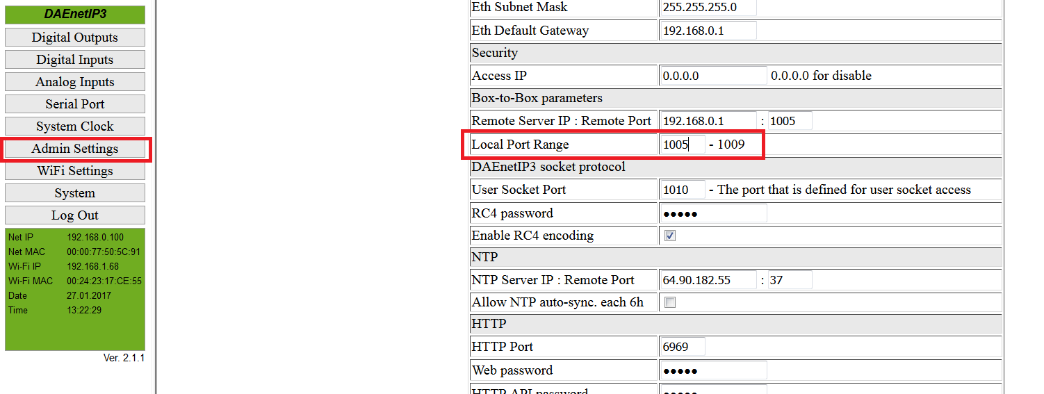
- Local Port Range - must mach with the flield "Remote Port" from the Input DAEnetIP3 board (by default it is 1005)
- Configuring the PortA outputs mode - it must be some of the following modes in order to accept commands from Input Module (DAEnetIP3): "On/Off & remote", "Inverting & remote", "Pulses & remote", "Timer & remote".
Configuring the output: Wi-Fi 16 Relay Module
- Sockets - socket_A must be configured as TCP-Server and port must mach with the Input Module "Remote Board Port" parameter (by default it is 8899)


