Cart is empty.
.png)


Denkovi Relay Manager v3 (DRMv3) is free software for easy controlling/configurating all kinds of Denkovi Modules.
Features
- DRMv3 Software can replace the following Denkovi software apps: DRM Software, USB 8 Relay Manager, Denkovi JExtraPack, USB 16 Relay Manager, USB 16 Relay Timer, DAEnetIP2 Manager, Denkovi USB 4 Relay Recorder, DAEnetIP3 Manager, Denkovi ModBus Tool, smartDEN Plotter
- Support most of the Denkovi modules
- Monitoring and control of all the inputs/outputs - digital outputs (relays), digital inputs, analog inputs, temperature sensors, analog outputs (PWM), garage doors
- Device configuration - parameters can be read, written, imported and exported to file or another device
- Powerful Cron based schedule mode for time events for setting outputs
- Full screen mode
- Lot of customizable inputs/outputs controls
- Customizable UI themes
- Notifications receiver - SNMPv1 Traps and MQTT
- Digital Outputs (Relays) can be controller by computer keyboard
- Outputs setting log
NON-suppored yet Denkovi Modules
Because the DRMv3 software supports most of the Denkovi modules, we list below only the non-supported yet devices from our portfolio:
|
Order number
|
Device status |
Relay board name and link
|
| DAE-USB_1WIRE | In production | USB to One Wire converter - Virtual Com Port FT232RL based |
| DAE-8RELAYS-1WIRE | In production | One wire relay card - 8 SPDT channels for Home Automation |
| DAE-8RELAYS-1WIRE-BOX | In production | One wire relay module - 8 SPDT channels for Home Automation - DIN BOX |
| DAEnetIP1 | Legacy | DAEnetIP1 - SNMP Ethernet controller with 28 digital/analog I/O |
| DAEnetIP1 + DAE-RB/Ro8-12V | Legacy | Web SNMP controlled 8 Relay Board v1 |
| DAE-PB-RO12/DI8/AI8 + DAEnetIP1 | Legacy | Internet/Ethernet 12 Channel Relay Board - I/O, SNMP, Web |
| DAEnetIP1 + DAE-RB/Ro4_v2 | Legacy | Web SNMP controlled 4 Relay Board |
Suppored OS
- Windows 7 and higher
- Linux
- Raspbian - Strech or Buster (Raspberry PI 3 and above)
- macOS Mojave and higher
Requirements
- Java - an OpenJDK (version 11 or higher) with integrated JavaFX - Liberica JDK (FULL JRE package), Azul JDK (JRE FX package)...
- For some Denkovi modules (USB for example) - additional drivers must be installed. Please refer to their documentation for more information;
- Minimal screen size: 1024 x 768 (can work on smaller resolution, but the UI is not optimized yet).
Installation and running
The first step must be done is to download the appropriate setup file for DRMv3.
| Version | Release date | Windows | Linux | Raspbian | macOS | ZIP only |
| 3.8 | 10.08.2023 |
|
* Includes DRMv3 software, drivers and Java.
** Includes DRMv3 software and instructions for drivers/Java.
*** Includes only DRMv3 software.
Version history may be downloaded from here
Windows
Just download the windows .exe file and run it.
After successful installation, the DRMv3 icon should be on your desktop, ready for running.
WARNING: Very often on Windows, .jar files are associated with programs other than Java Virtual Machine (usually with archivators) which will prevent opening DRMv3 from the icon with double click (but only from command line with the java -jar command). This can be fixed easily when google and search "how to open jar files in windows"
Linux
Download and extract DRMv3.tar lets say in /home/user/Downloads/DRMv3-Linux/
Instructions for Java and drivers (if any required) installation are included inside the archive.
If you don't have OpenJDK with JavaFX integrated, download it from Liberica JDK (FULL JRE package) or Azul JDK (JRE FX package)
After that the downloaded java pckage must be extracted.
To run the software, we execute the below command (replacing with the respective paths to files):
/home/user/Downloads/jre-20.0.1-full/bin/java -jar /home/user/Downloads/DRMv3-Linux/DRM_v3.jar
Please note: It is not recommended to run with sudo because this would require additional more complex parameters set to run the software. You might be interested to read also our article "Accessing USB Relay Boards without Sudo in Linux"
Raspbian
Please check the Linux section above.
Please note: Raspbian OS is not the perfect option to run DRMv3 since it uses JavaFX and it requires more resources for the graphics. Here still remains the rule: the bigger Raspberry PI, the better. We tested with Raspberry PI 3 (Strech) and Raspberry PI 4 (Buster) and for both relatively stable. Of course Raspberry PI 4 with 8GB RAM works quite better.
We also tried to describe all the steps during the installation and running all the packages and libraries for Raspbian, but it still may be additional/different things to do. Please contact us if you find something so we can update the documentation for rest of the users.
macOS
The same as the Linux steps, but just download DRMv3.zip file.
Finally, we should get the splash screen.
UI overview

- Menu bar - open/save files, program settings, program skins etc;
- Device name and firmware version (if available);
- Devices tab - access current selected device resources;
- Notifications tab - monitoring of the notifications, sent by some device;
- Monitoring and Control tab - access to the device I/O resources (relays, analog inputs, digital inputs etc);
- Timers and Pulses tab - access timers, schedules, pulses. Available only for devices with outputs;
- Configuration tab - access the device configuration parameters via some protocol. Available only for some devices;
- Tools - various tools;
- Connection Settings - the settings that are needed for the software to be connected with the device (ip address, port, password etc);
- Device image;
- Device list - contains list with all currently opened devices;
- Available devices list - list with all available device models;
- Add - add new device to the list;
- Delete - delete the selected device from the list;
- Reboot - reboot the device (software reset), only if supported by the device;
- Copy - copy selected device and add it to the list;
- Del all - delete all devices from the list;
- Refresh - read the i/o values for the selected device and refresh them in the UI;
- Enable Auto Refresh - enable/disable refreshing of the i/o values automatically (periodically, via the specified refresh interval);
- Sample i/o visualization;
- Status bar - show the connection status, current time, last seen time, error messages etc;
- I/O tabs - device i/o are grouped into tabs as digital outputs, digital inputs, analog inputs etc. Every device may have different number of i/o in each group and not all groups may be present in each device. These tabs depend on the device i/o resources.
Connection Settings
Buttons

- Test Connection - this will test if the software is able to connect to the device, based on the entered settings;
- Connect - connect to the device. After the device is with status CONNECTED, we can work with it;
- Disconnect - disconnect from the device.
Common settings
These settings are available for all devices.
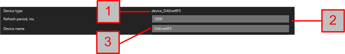
- Device type - the main type of the device. Below they are described the settings for every device type separately;
- Refresh period, ms - the refresh period between i/o values readings;
- Device name - the name of the device shown in the software.
warning: Some devices can appear as more than one device type as they support more than one protocol. For example smartDEN Opener - XML (device_XML) and smartDEN Opener - MQTT (device_MQTT). In such cases the user can select the most suitable connection type.
Also all devices with digital outputs (relays), have the following option:

When it is unchecked - single command, checked - multiple command. Single command sets only one output, while multiple command sets all outputs at a time. Single command does not affect hardware timers, but timings are less precise. Multiple command affects hardware timers, but the timings are more precise. This option is reasonable only if there are more than one pulsing digital outputs lines at the same moment.
Settings for device_DAEnetIP3
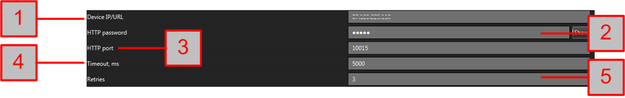
- Device IP/URL - it can be IP address or DNS name of the device (by default 192.168.1.100);
- HTTP API password - must be the same password from DAEnetIP3 web server -> Admin Settings -> HTTP -> HTTP API password (by default admin);
- HTTP port - the HTTP port on which the DAEnetIP3 web server can be found (by default 80);
- Timeout,ms - the connection timeout in milliseconds;
- Retries - the number of retries to connect after unsuccessful connection before give up;
Settings for device_SNMP
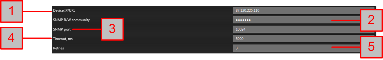
- Device IP/URL - it can be IP address or DNS name of the device;
- SNMP R/W community - can be found from the device web server settings (depending on the device model);
- SNMP port - the SNMP server listening port of the device (by default 161);
- Timeout,ms - the connection timeout in milliseconds;
- Retries - the number of retries to connect after unsuccessful connection before give up;
Settings for device_XML
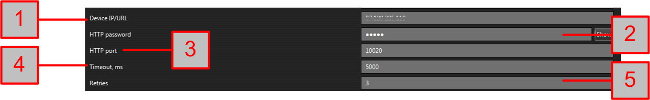
- Device IP/URL - it can be IP address or DNS name of the device;
- HTTP password - usually it can be found from the device web server -> General Settings -> Password (by default admin);
- HTTP port - the HTTP server listening port of the device. Usually it can be found from the device web server -> HTTP/XML/JSON Settings -> Web HTTP port (by default 80);
- Timeout,ms - the connection timeout in milliseconds;
- Retries - the number of retries to connect after unsuccessful connection before give up;
Settings for device_XML (smartDEN Logger)
The settings are the same as device_XML but including one more parameter - the directory where the downloaded logs from the smartDEN Logger are stored.

WARNING: It is strongly recommend every smartDEN Logger device to be with different local directory.
Settings for device_FT245

Here we need to select just the FT245RL ID of our board from the drop down menu.
WARNING: For Linux/Raspbian OS it is highly possible at the first moment the software not to detect the FTDI board chip ID. To solve this issue, we need to:
- Execute the following commands every time after the board is connected to the computer rmmod ftdi_sio and rmmod usbserial as root user;
- Follow this tutorial - http://denkovi.com/accessing-usb-relay-boards-without-sudo-in-linux
Settings for device_MCP2200

- MCP2200 ID - the ID of the board of our board from the drop down menu;
- Save relay states - if this option is enabled, when setting the relays, their states will be saved in EEPROM and will be restored after board is booted. This is also used to predefine the relays boot states.
WARNING: For Linux/Raspbian OS it is highly possible at the first moment the software not to detect the MCP2200 board chip ID. To solve this issue, we need to:
- Follow this tutorial - http://denkovi.com/accessing-usb-relay-boards-without-sudo-in-linux
Settings for device_VCP
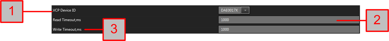
- VCP Device ID - the FTDI FT232RL Chip ID (Device ID) of the board;
- Read Timeout, ms - read timeout. Normally it shouldn't be changed;
- Write Timeout, ms - write timeout. Normally it shouldn't be changed.
WARNING: For Linux/Raspbian OS it is highly possible at the first moment the software not to detect the FTDI board chip ID. To solve this issue, we need to:
- Execute the following commands every time after the board is connected to the computer rmmod ftdi_sio and rmmod usbserial as root user;
- Follow this tutorial - http://denkovi.com/accessing-usb-relay-boards-without-sudo-in-linux
Settings for device_WiFi16
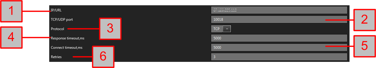
- Device IP/URL - it can be IP address or DNS name of the device;
- TCP/UDP port - it can be found from the device web server -> Sockets -> SOCKET_A Settings / SOCKET_B Settings Port ID (by default 8899);
- Protocol - TCP or UDP, depending on the desired preference;
- Response timeout,ms - the response timeout in milliseconds;
- Connection timeout,ms - the connection timeout in milliseconds;
- Retries - the number of retries to connect after unsuccessful connection before give up.
Settings for device_modbus_tcp
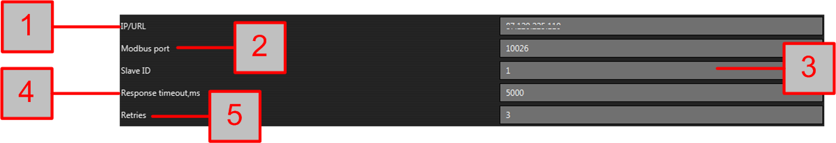
- IP/URL - it can be IP address or DNS name of the device;
- Modbus port - it can be found from the device web server -> Sockets -> SOCKET_A Settings / SOCKET_B Settings Port ID (by default 502);
- Slave ID - the modbus slave id of the device;
- Response timeout,ms - normally it shouldn't be changed;
- Retries - the number of retries to connect after unsuccessful connection before give up.
Settings for device_modbus_vcp
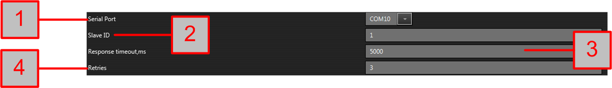
- Serial Port - the serial port of the board;
- Slave ID - the modbus slave id of the device;
- Response timeout,ms - normally it shouldn't be changed;
- Retries - the number of retries to connect after unsuccessful connection before give up.
Settings for device_mqtt
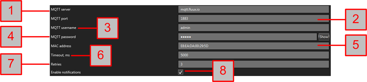
- MQTT server - it can be IP address or DNS name of the MQTT server (broker);
- MQTT port - the port of the MQTT server (by default 1883);
- MQTT username - can be found on the device web server (by default admin);
- MQTT password - can be found on the device web server (by default admin);
- MAC address - the MAC address of the device;
- Timeout,ms - the connection timeout in milliseconds;
- Enable notifications - flag for enable/disable notifications receiving for this device by the DRMv3 software.
WARNING: Encrypt topic option from MQTT Settings page from the device web server must be turned on in order DRMv3 to communicate with the device via MQTT protocol.

Status bar
Connection status

It can be the following:
- CONNECTED - it means the device is connected and we can work with it;
- CONNECTING - the software is still trying to connect to the device and we can not work with it until we connected to it;
- DISCONNECTED - the device is disconnected and we can not work with it until we connected to it.
Last seen status

Indicates when the device was seen for last time. Date/Time format can be adjusted ftom Settings -> Application Settings -> Date/Time Format.
Date/Time

System Date/Time. Date/Time format can be adjusted ftom Settings -> Application Settings -> Date/Time Format.
Error status

It shows detailed error message. Usually this explains the reason why is not possible to connect to the device.
Retries

It shows the number of the current connection attempt (given by Connetion Retries parameter if available) to the device before error message appear and status become CONNECTING.
Information status

Detailed information about the current request to the device.
Menu bar
File
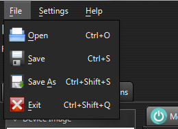
- Open - open existing file with devices;
- Save - save current file with devices;
- Save As - save current file witdh devices under different name;
- Exit - exit from program.
Settings
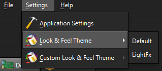
- Application Settings - opens window with software settings;
- Look & Feel Theme - changes the software UI theme (skin) from the built-in list;
- Custom Look & Feel Theme - changes the software UI theme (skin) from the list defined by the user.
Help
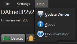
- Update Devices - update available device models list (if available);
- About - information about current version;
- Documentation - link to this document.
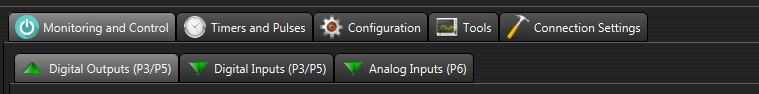
Monitoring and Control
This tab is for monitoring and control the inputs and outputs of the selected device.
Please note: Only supported inputs/outputs will be populated for the selected device. The rest will be hidden.
Please note: The name of each input/output tab for each device may be different. For example for DigitalOutputs for DAEnetIP3 device may be Digital Outputs (PortA) for DAEnetIP2 device may be Digital Outputs (P3/P5) and so on.
Common buttons

- Refresh button - it refreshes the i/o states manually;
- Enable Auto Refresh - enable/disable refreshing of the i/o values automatically (periodically, via the specified refresh interval). If enabled, the io values are retrieved from the device - the feedback is real, but there is a delay. If disabled, the io values are retrieved via the software - it is faster, but there is no real feedback.
Full screen mode
On the selected I/O tab -> right click -> select the monitor (if more than one)
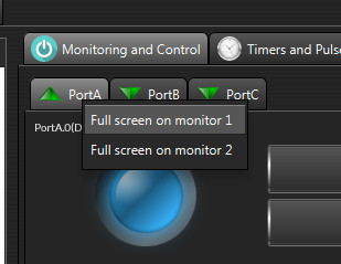
- For exit from full screen mode - press ESC;
- To switch between other I/O screens in full screen mode - use the arrows keys;
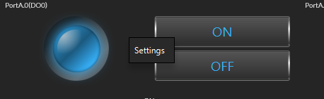
Settings
To edit the settings for some i/o -> right click with the mouse -> from the pop-up menu -> Settings
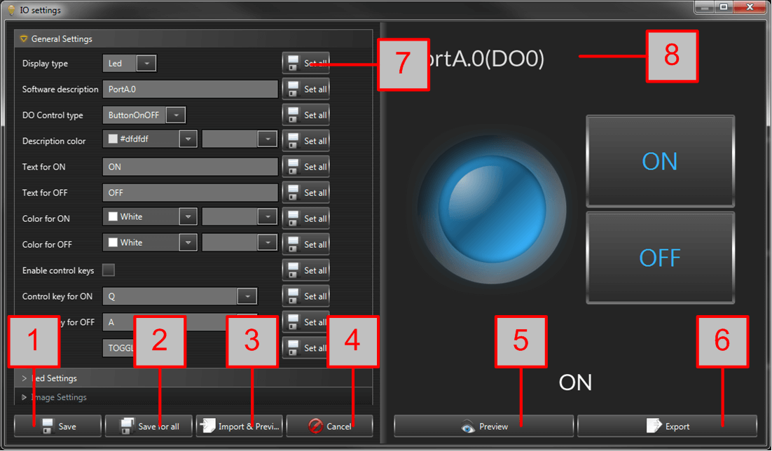
- Save - saves the settings for this i/o pin;
- Save for all - saves the settings for all i/o pins for this port;
- Import and Preview - imports settings from file. It must be the same i/o type and same device model;
- Cancel - no changes are made;
- Preview - preview the settings into the preview panel;
- Export - saves (exports) the current i/o settings into file;
- Set all - saves immediately this parameter with the current value to all other i/os from same port;
- Preview panel - displays the current settings;
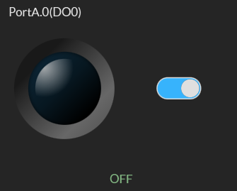
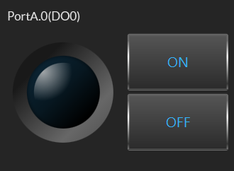
Digital Outputs
By default, the digital outputs are like the image below - with simple LED indicator and button for ON/OFF.

- ON/OFF indicator;
- ON - turns the output ON;
- OFF - turns the output OFF;
- ALL ON - turns all outputs ON;
- ALL OFF - turns all outputs OFF;
- Description - it shows the software (and hardware if supported) description of this output;
- Set All - sets all the digital outputs at once (with single command if available). This is valid only if the output DO Control type is "CheckBox";
- Output status;
General Settings
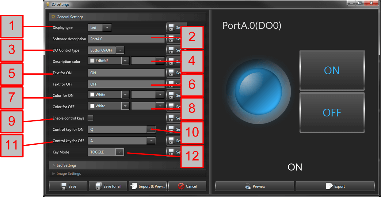
- Display type:
- Led - led like visualization;
- Image - user defined image for ON and OFF;
- Software description - user friendly text for every output;
- Do Control type:
- ButtonOnOff - output is controlled via button for ON and button for OFF;
- CheckBox - firstly, the checkboxes are adjusted ON/OFF and secondly the "SetAll" button is pressed to send the command;
- Descrption color - set the color of description text;
- Text for ON - text for ON button and ON status;
- Text for OFF - text for OFF button and OFF status;
- Color for ON - color for ON status;
- Color for OFF - color for OFF status;
- Enable control keys - enables/disables the function to control output via computer keyboard;
- Control key for ON;
- Control key for OFF;
- Key Mode:
- TOGGLE - the relay is switched in ON when key for ON is pressed and switched OFF when key for OFF is pressed;
- MOMENTARY - Control key for ON and Control key for OFF must be equal. The output is ON while the the key is pressed only.
Led Settings
These settings are applicable when the Display type is "Led";
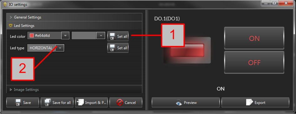
- Led color;
- Led type - it can be ROUND, SQUARE, VERTICAL, HORIZONTAL;
Image Settings
These settings are applicable when the Display type is "Image";
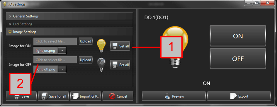
- Image for ON;
- Image for OFF;
Digital Inputs
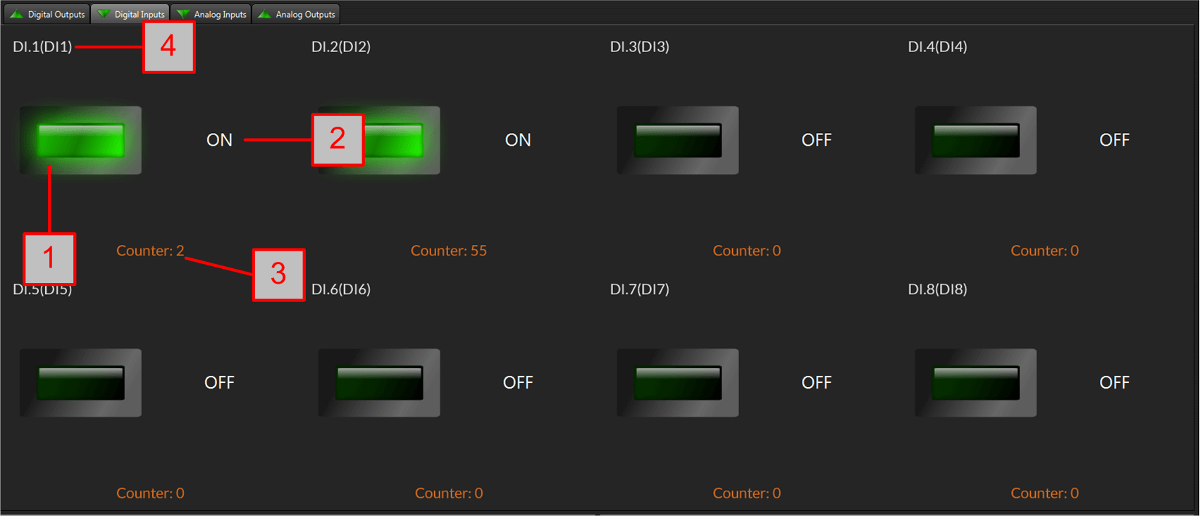
- ON/OFF indicator;
- ON/OFF text;
- Counter value (if available);
- Description - it shows the software (and hardware if supported) description of this input;
NOTE: The settings for Digital Inputs are the same like those for Digital Outputs with the difference that here there are not key controls.
Analog Outputs
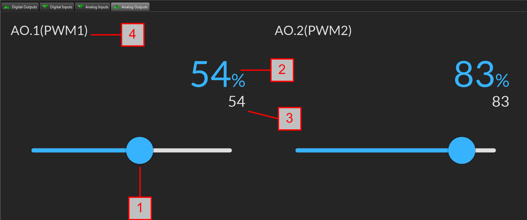
- Slider - the Analog Output control for changing the level;
- Percent;
- Feedback value - this is the actual value read from the device;
- Description - it shows the software (and hardware if supported) description of this output;
Analog Outputs General Settings

- Software description - user friendly text for every output;
- Descrption color - set the color of description text;
- Slider color;
- Units color;
- Value color;
Garage Door Outputs
INFormation: This control is mainly for smartDEN Opener device.
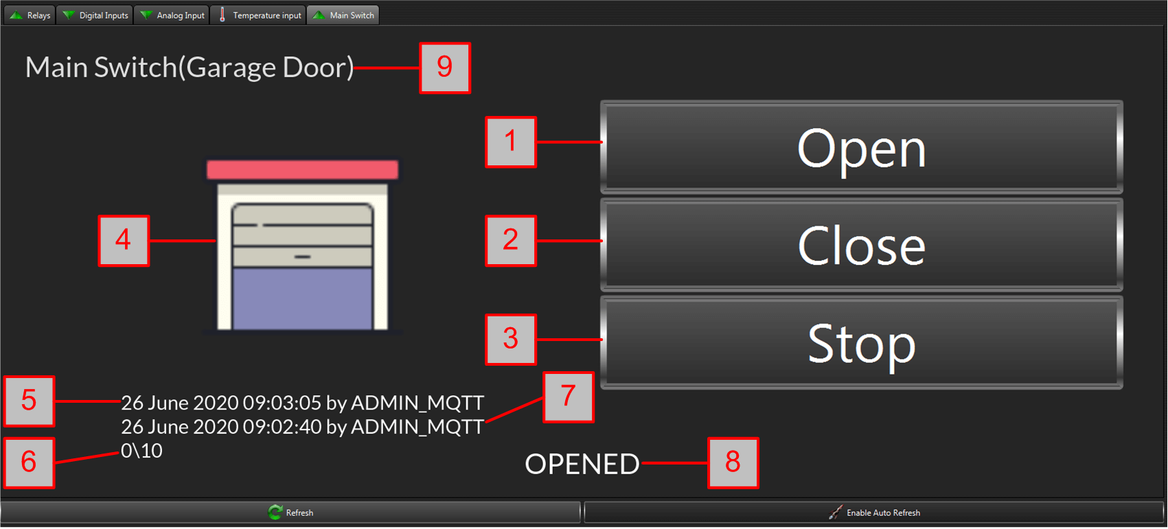
- Open - the button sends command for open the unit;
- Close - the button sends command for close the unit;
- Stop - the button sends command for stop the unit;
- Unit image;
- Last opened date/time;
- Progress of opening/closing;
- Last opened date/time;
- Status (value) of the unit;
- Description - it shows the software (and hardware if supported) description of this output;
Garage Door General Settings

- Software description - user friendly text for every unit;
- Descrption color - set the color of description text;
- Info color - the color for last closed/opened;
- Value color - the status (value) color;
- Text for close;
- Text for open;
- Text for stop;
- Opening image;
- Closing image;
- Opened image;
- Closed image;
- Stopped image;
Analog / Temperature Inputs
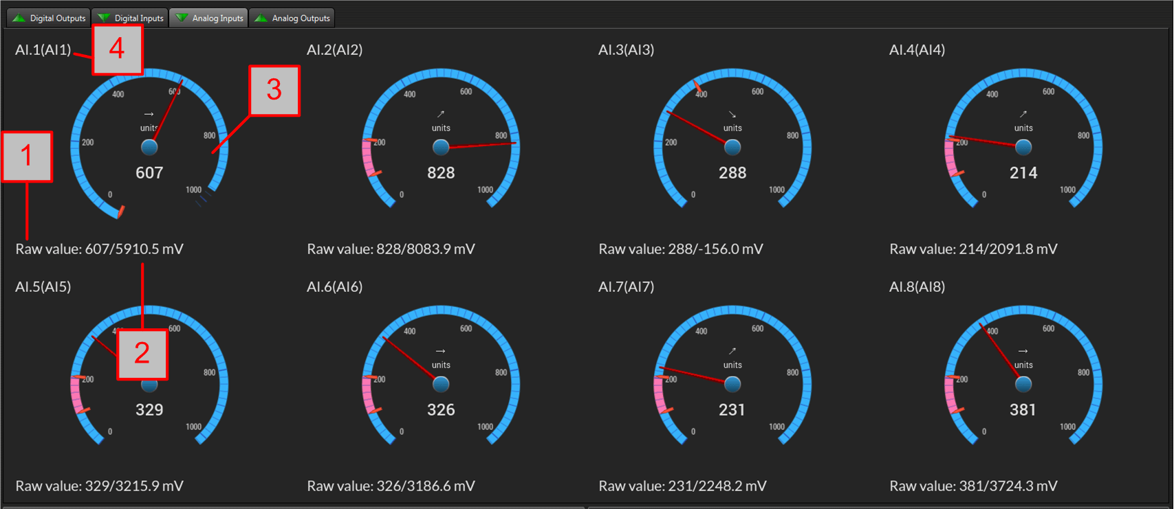
- Raw value - the value received directly from the analog (ADC) / temperature input;
- Hardware scaled value - the valued and units received from the hardware scaling from the device (available only for only devices);
- Indicator;
- Description - it shows the software (and hardware if supported) description of this output;
General Settings
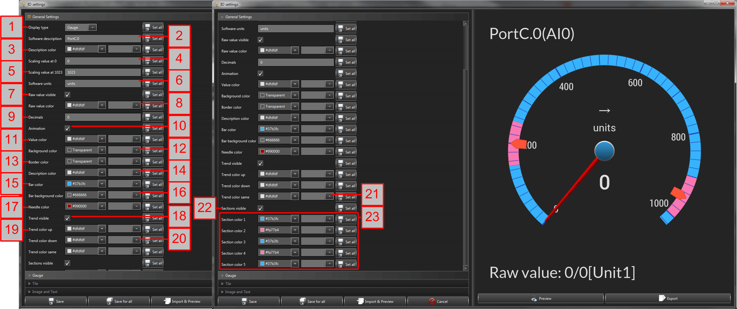
- Display type - there are three types of indicators: Gauge, Tile, Image_Text;
- Software description - user friendly text for every unit;
- Descrption color - set the color of description text;
- Scaling value at 0 - used for software scaling;
- Scaling value at 1024 - used for software scaling;
- Software units;
SOftware scaling (done by DRMv3 software): If we assume that Scaling value at 0 is V1, Scaling value at 1024 is V2, current measured raw value is X, then the software scaled value Y is calculated like this: Y = X * (V2 - V1) / 1024 + V1. This is the value used for the indicators;
- Raw value visible - enables/disables the raw value indication;
- Raw value color - color of the raw value;
- Decimals - the number of decimal digits after the decimal separator;
- Animation - enables/disables the animation effects;
- Value color - color of the value;
- Background color - color for the background of the indicator;
- Border color - color for the indicator border;
- Descrption color - sets the color of description text;
- Bar color - color for the bar element of the indicator (if available);
- Bar background color - background color for the bar element of the indicator (if available);
- Needle color - color for the needle of the indicator;
- Trend visible - enables/disables the trend showings;
- Trend color up - the color for up trend;
- Trend color down - the color for down trend;
- Trend color same - the color for down trend;
- Sections visible - enables/disables sections (if any). Sections are based on the hysteresis and thresholds for the input. Some devices supports low/high hysteresis and low/high thresholds, some only low/high thresholds and others don't support at all (for them there are not sections).
Please note: Not all parameters are available for all devices, indicator types and sub-types.
- Sections for this device (if any)
Gauge Settings

- Display type - the subtype of the gauge indicator. Some examples:
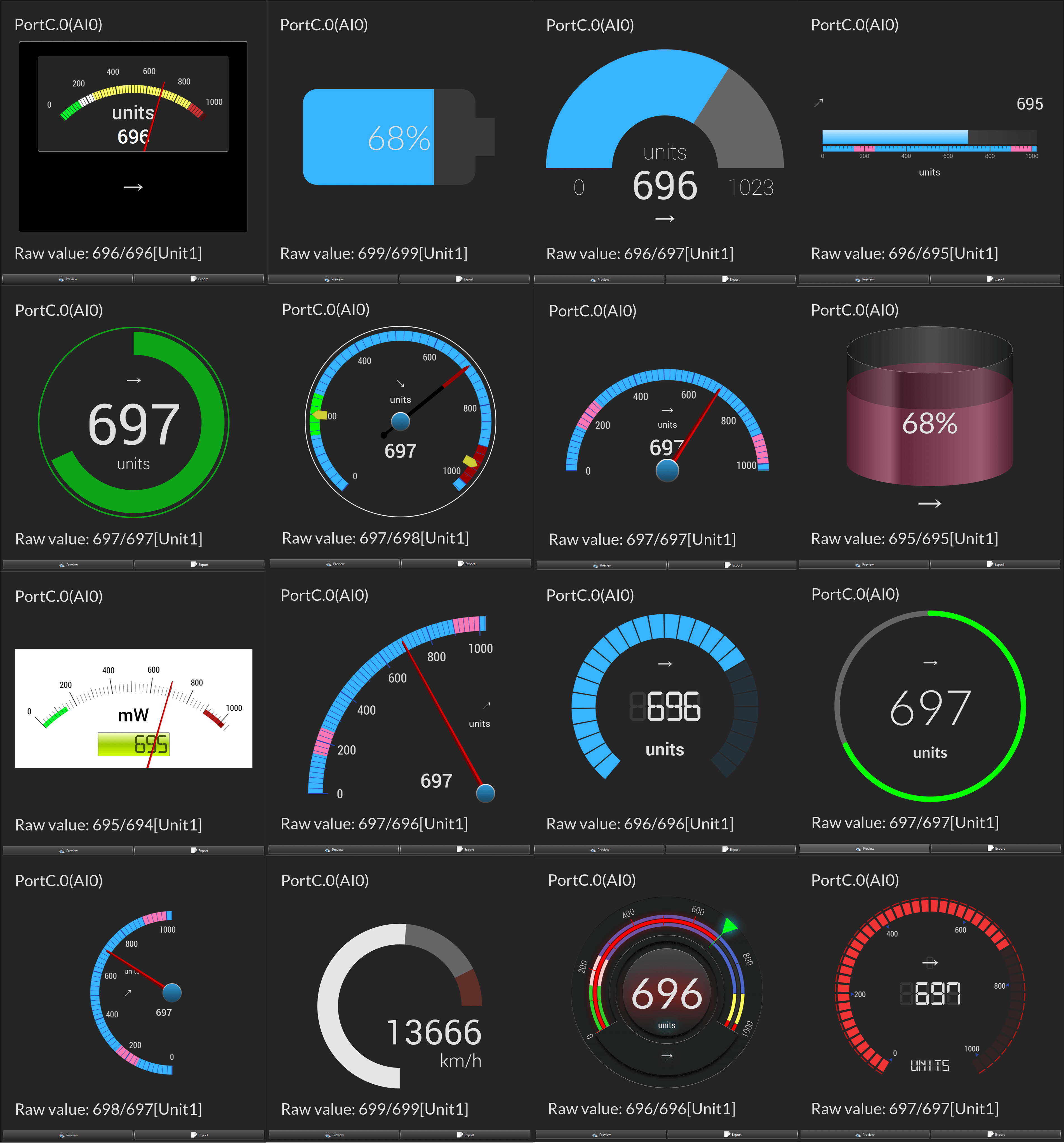
- Orientation - some indicators may be flipped - horizontally or vertically;
- Markers type - the type of the marker;
- Marker/threshold color - the color of the marker/threshold;
- Tick label color - the color of the gauge tick labels;
- Tick mark color - the color of the tick label mark;
- Zero color - the color of the zero digit of the indicator;
- Threshold % (for SpaceX) - the threshold level (for the spaceX indicator only);
- Needle type;
- Needle shape;
- Needle size;
- Major tick type;
- Major tick color;
- Medium tick type;
- Medium tick color;
- Minor tick type;
- Minor tick color;
- Knob type - the type of the knob for the needle;
- Knob color - the color of the knob for the needle;
- LCD visible - enables/disables the LCD inside the indicator. Some indicators supports small LCD sub-indicator instead of text:
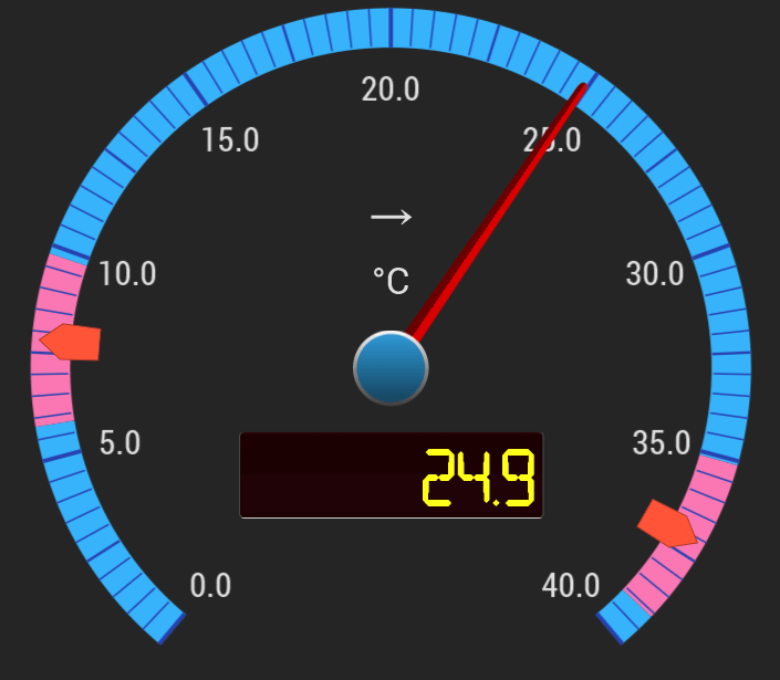
- LCD type - different colors of LCD panels, for example:
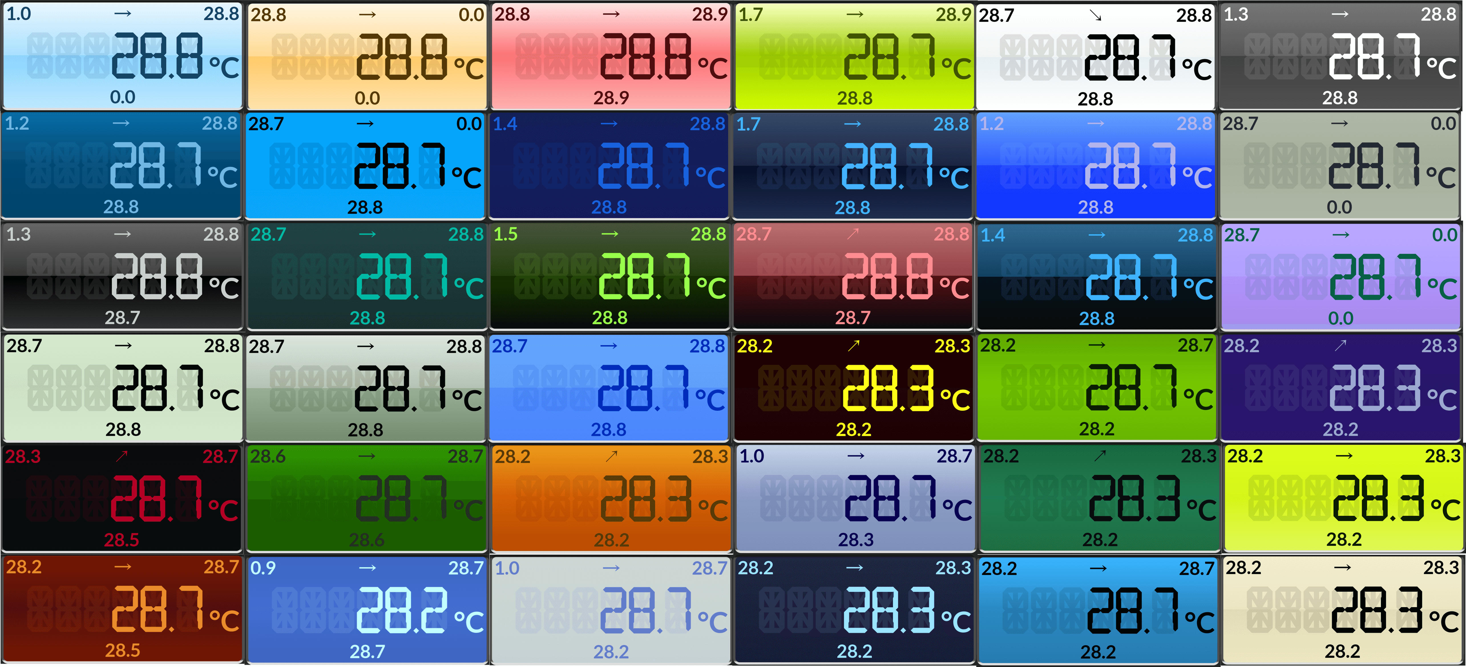
LCD type SECTIONS: The type SECTIONS colors the display background based on the set sections colors in General Settings;
- LCD font - the font for the LCD text;
Tile Settings
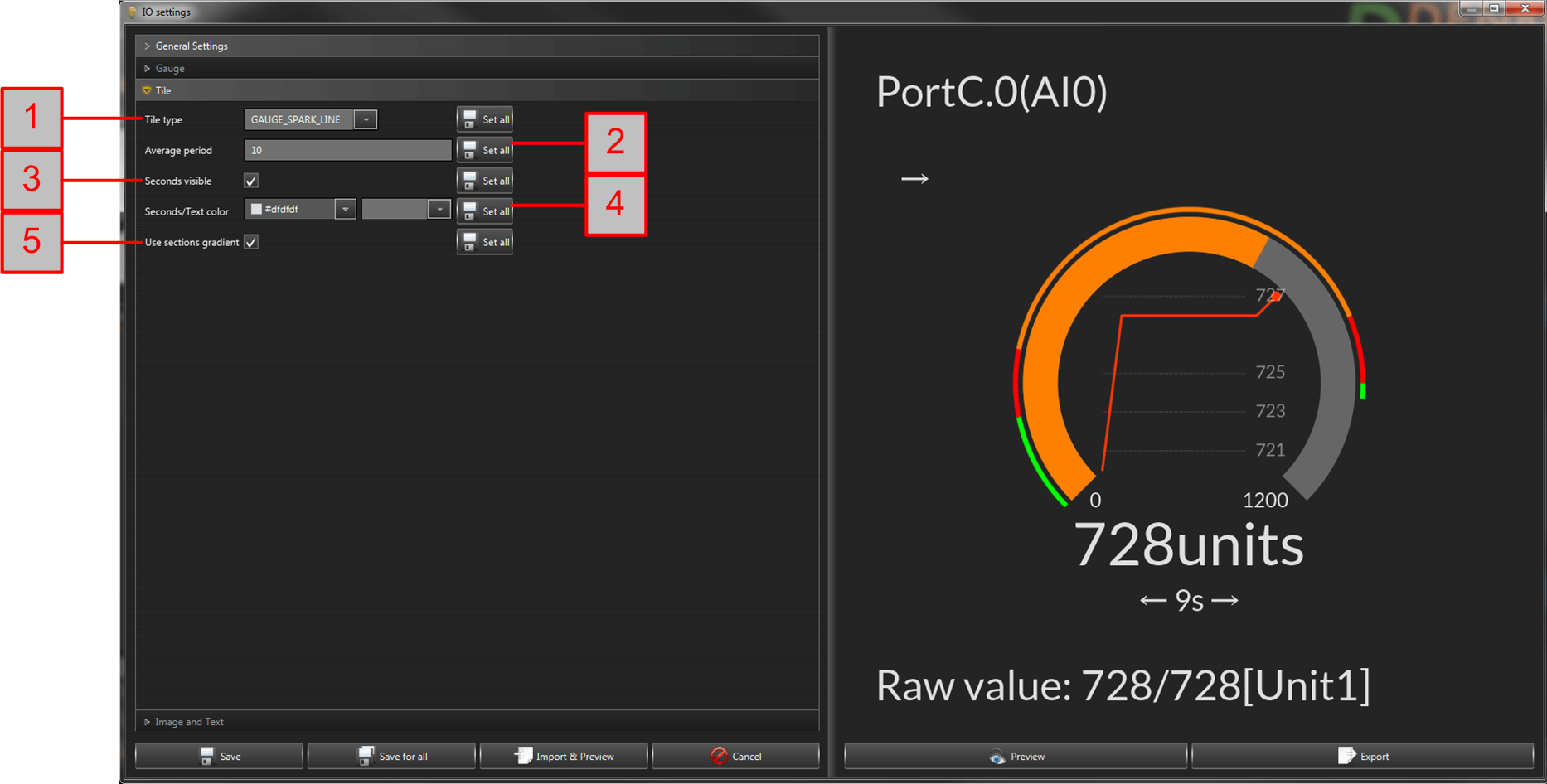
- Tile type - possible types:
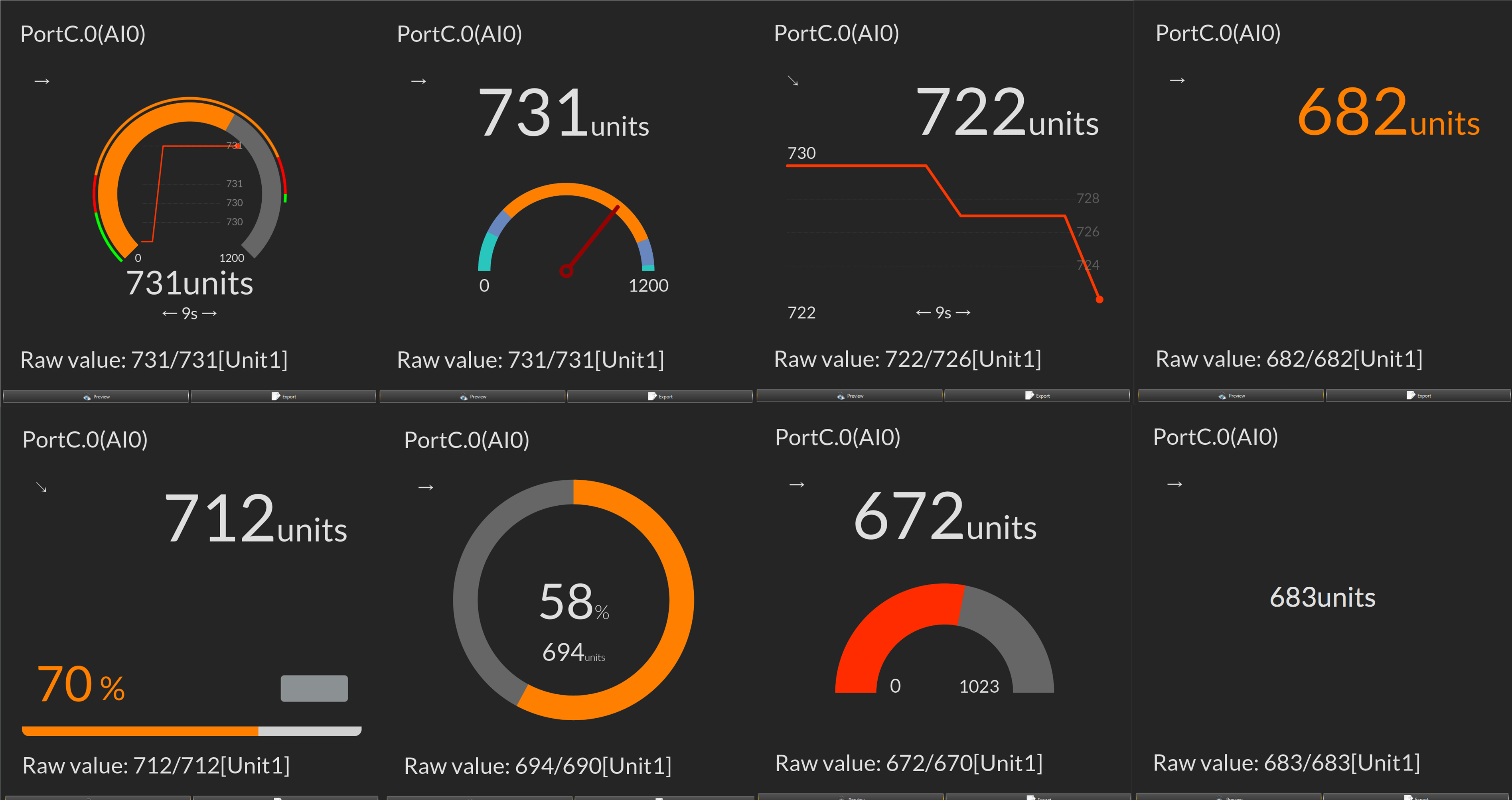
- Average period - the history of the chart inside the tile;
- Seconds visible - enabled/disables seconds;
- Seconds/Text color - the color of the seconds and text labels;
- Use sections gradient - if enabled the chart / bar are with color gradients;
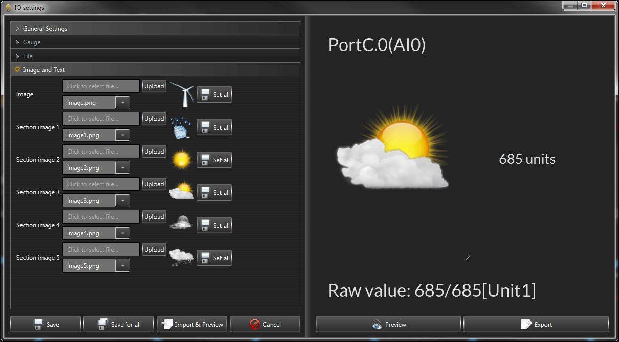
Image_Text Settings
With this type, it is possible to upload custom image for the input. If the device supports thresholds and hysteresis then it can be also different image for each section.
Timers and Pulses
In this section it is possible to make timers and pulses for the outputs of the device. If no outputs are available then it is inactive.
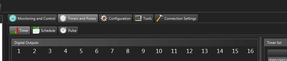
Timer
This is the same timer mode from the old DRM software. The difference here is that the analog outputs (PWM) and garage door outputs can be controlled as well. Basicly with this mode we can set outputs in certain state for specific time of period.
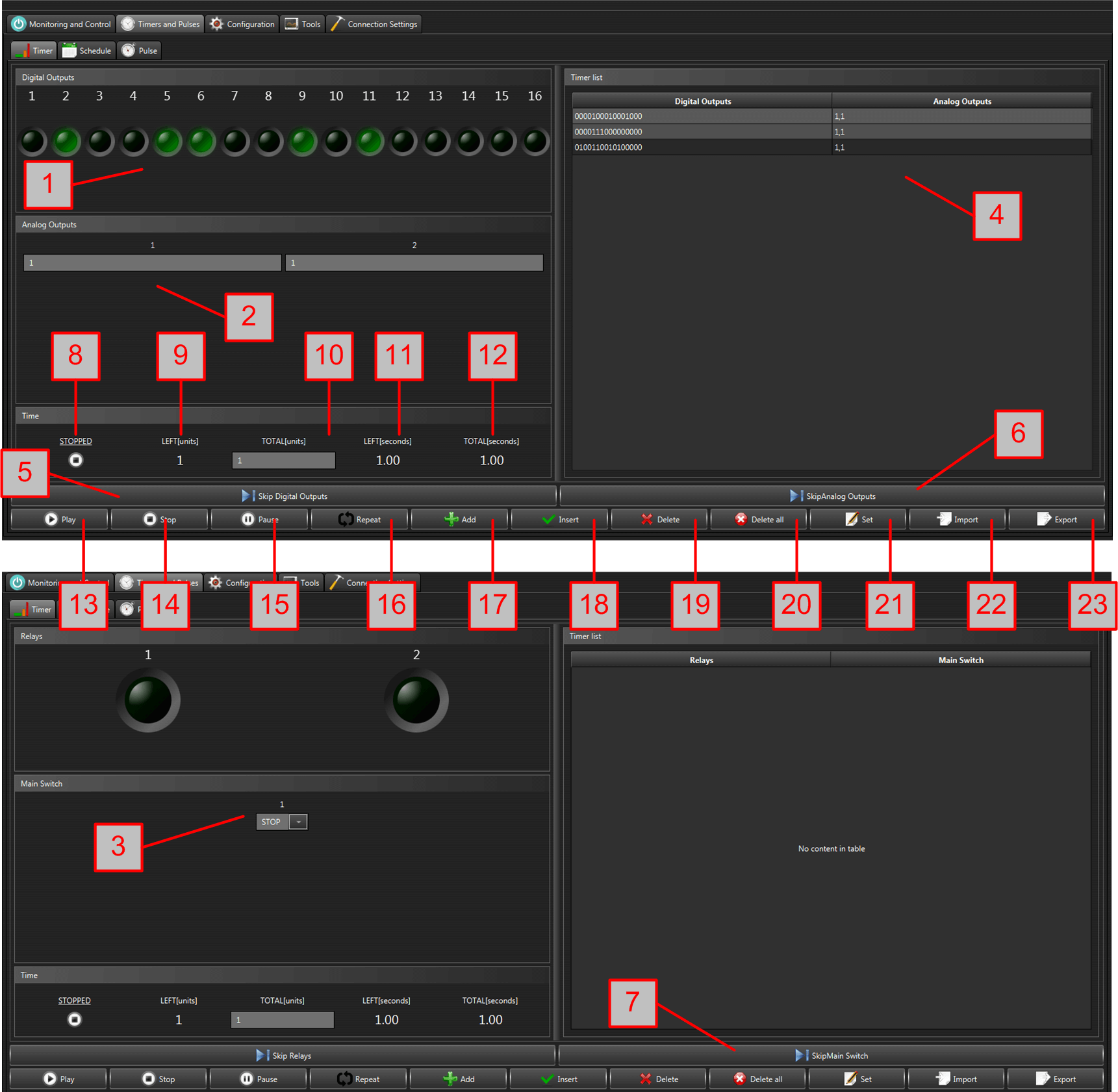
- Digital Outputs (Relays) state - with these buttons we set the digital outputs (relays) state - ON or OFF;
- Analog Outputs (PWM) state - here we set the level of the analog outputs (PWM);
- Garage door state - we set it to OPEN, CLOSE or STOP;
- Timer list - it contains the list with all outputs states;
- Skip Digital Outputs - if enabled, the digital outputs (relays) commands will be skipped during the running of the timer program;
- Skip Analog Outputs - if enabled, the analog outputs (PWM) commands will be skipped during the running of the timer program;
- Skip Main Switch - if enabled, the garage door outputs commands will be skipped during the running of the timer program;
- Timer state;
- Left units;
- Total units;
- Left seconds;
- Total seconds;
- Play - starts the timer;
- Stop - stops the timer;
- Pause - makes pause of the timer;
- Repeat - if enabled, it will repeat the timer;
- Add - adds new timer state;
- Insert - inserts new timer state;
- Delete - deletes the selected timer state;
- Delete all - clears the timer list;
- Set - changes the selected timer state;
- Import - imports (loads) timer from file;
- Export - exports (saves) timer to file;
Schedule
The schedule is Cron (Quarzt) library based mode for controlling device outputs.
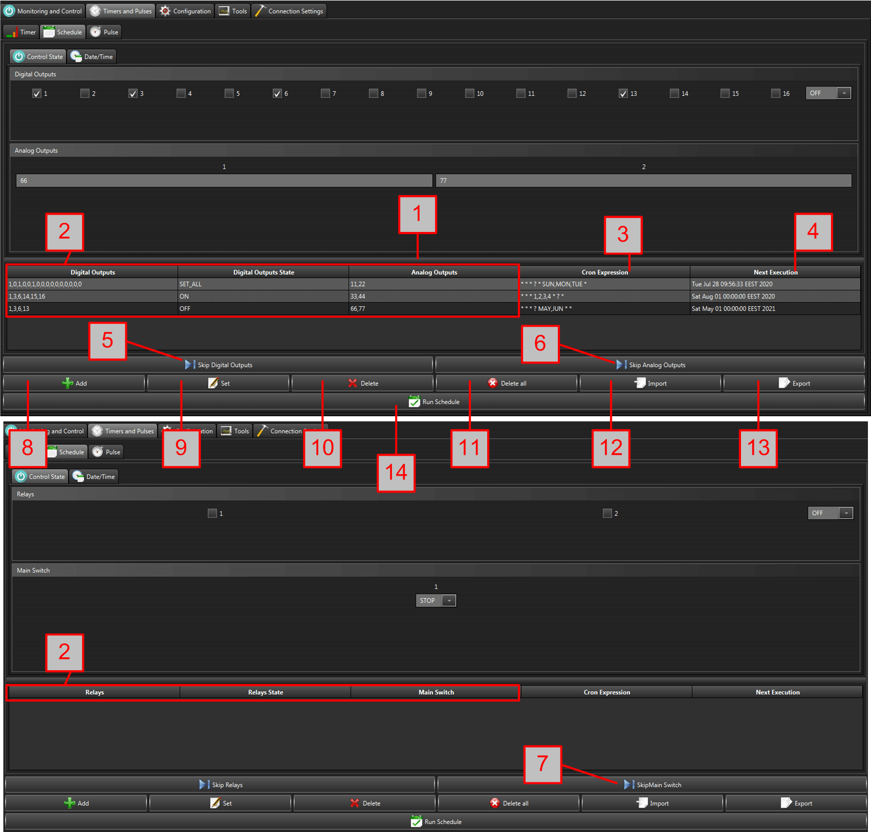
- Schedule list - it contains outputs state, when they will be set and eventually the next execution;
- Outputs state - the digital, analog and garage outputs state;
- Cron Expresion - Cron string code generated by the UI;
- Next Execution - the next execution of the event;
- Skip Digital Outputs - if enabled, the digital outputs (relays) commands will be skipped during the running of the timer program;
- Skip Analog Outputs - if enabled, the analog outputs (PWM) commands will be skipped during the running of the timer program;
- Skip Main Switch - if enabled, the garage door outputs commands will be skipped during the running of the timer program;
- Add - adds new state;
- Set - changes the selected state;
- Delete - deletes the selected state;
- Delete all - clears the schedule list;
- Import - imports (loads) file;
- Export - exports (saves) file;
- Run Schedule - activate the schedule;
Control State
From this tab, we generate the outputs state.
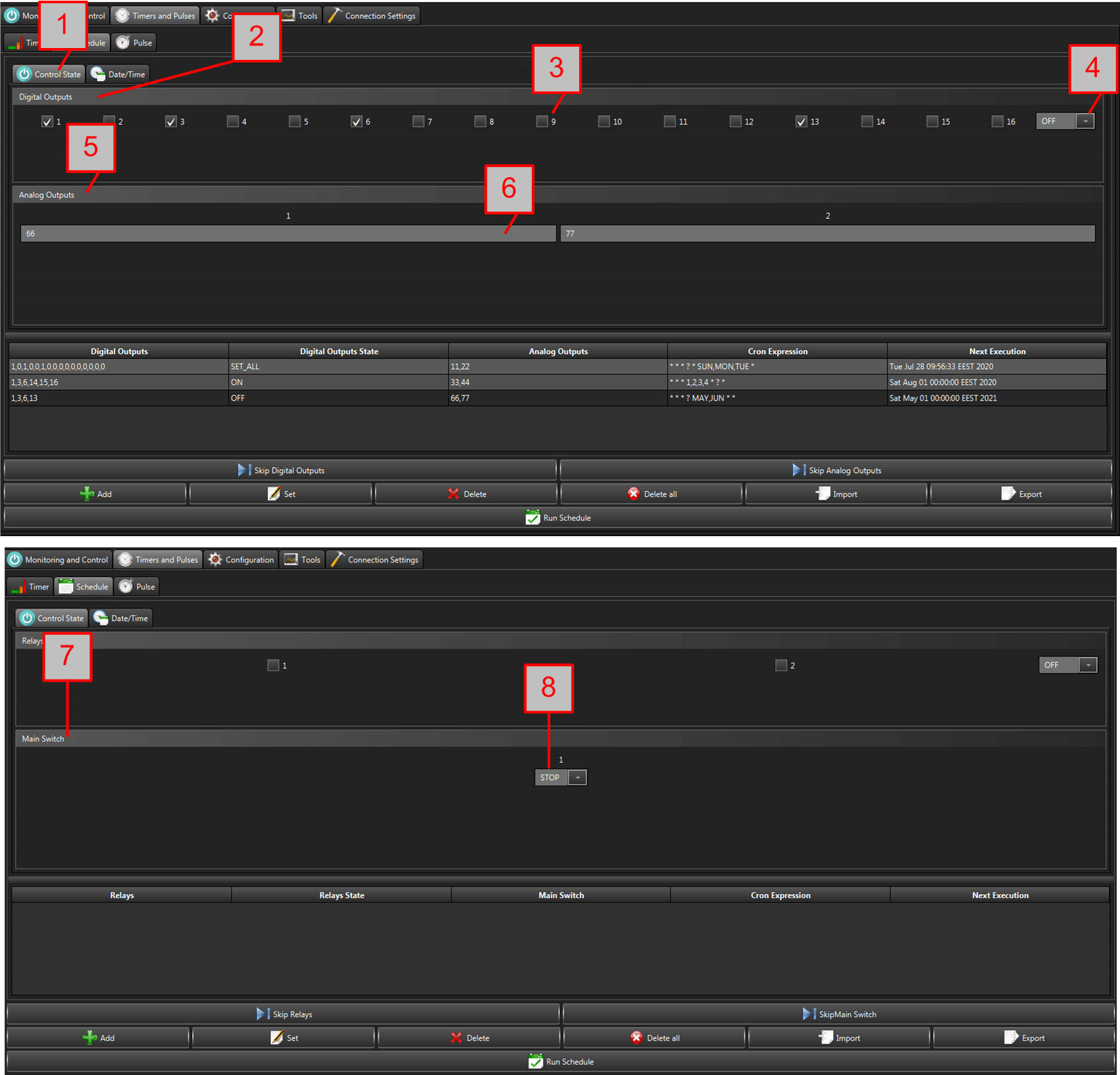
- Control State tab;
- Digital Outputs group;
- Check box for each digital output;
- Setting mode - ON, OFF, SET_ALL. ON/OFF - it will set only the selcted outputs into ON/OFF. SET_ALL - it will set all the outputs as per the selected check boxes;
- Analog Outputs group;
- Text field for each analog output value;
- Garage door output group;
- State for the garage door output;
Date/Time
From here we adjust the date/time of the event.

- Cron expression visualization - for reference;
- Seconds, Minutes, Hours, Day, Month, Year settings;
Pulses
This mode is for digital outputs only. It makes ON and OFF pulses for certain amount of cycles. If no digital outputs, it is disabled.
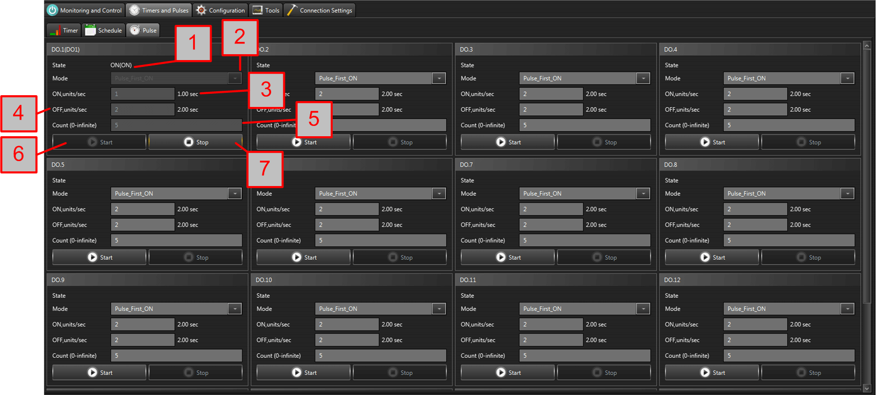
- State - the current state of the output - ON or OFF;
- Pulse mode:
- Single_Pulse_ON - makes single pulse, starting with ON;
- Single_Pulse_OFF - makes single pulse, starting with OFF;
- Pulse_First_ON - makes pulses, starting with ON;
- Pulse_First_OFF - makes pulses, starting with OFF;
- ON, units/sec - the ON period in units and seconds;
- OFF, unit/sec - the OFF period in units and seconds;
- Count (0-infinite) - the number of pulses. If 0, it means infinite cycling;
- Start - start pulses;
- Stop - stop pulses;
Configuration
This tool is to configure the parameters of the device. It is possible to read, write, import from file and export to file the parameters of the device.
Please note: The tab is active only when the device supports configuration.
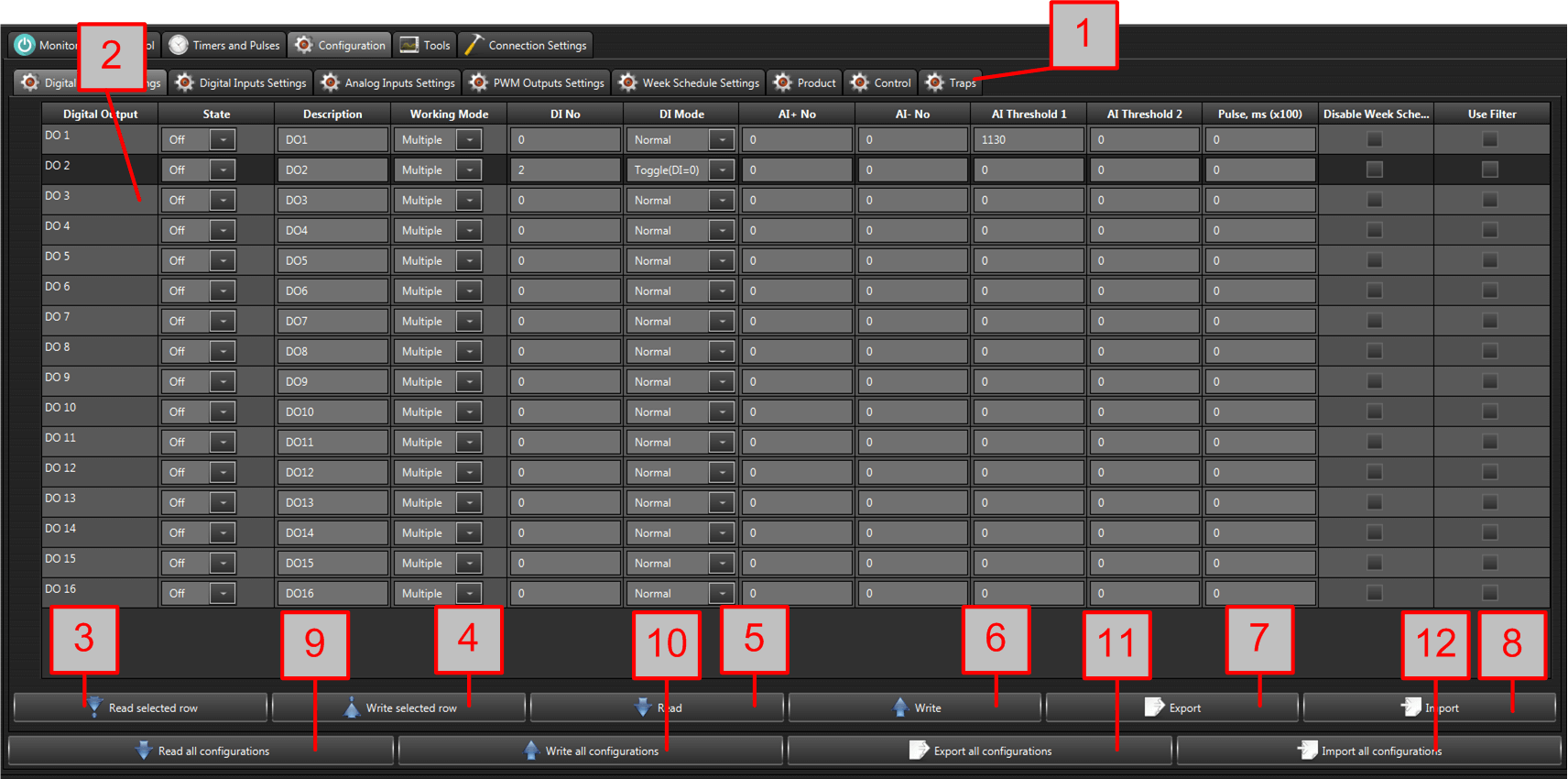
- Configuration tabs (groups) - different type and number for each device type, depending of what parameters are supported for configuration;
- Configuration parameters in the selected group;
- Read selected row - reads the selected row only from the device to the table;
- Write selected row - writes the selected row only from the table to the device;
- Read - reads all the parameters from the device to the selected group;
- Write - writes all the parameters from the selected group to the device;
- Export - saves the selected group parameters to file;
- Import - loads the selected group parameters from file;
- Read all configurations - reads all the configuration parameters from the device;
- Write all configurations - writes all the configuration parameters to the device;
- Export all configurations - saves all the parameters to file;
- Import all configurations - loads all the configurations from file;
Tools
Outputs Setting Log
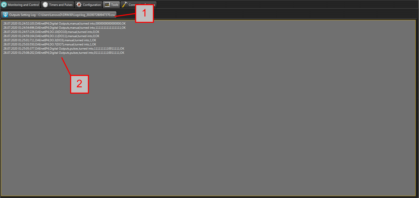
- Output Setting Log tab
- Log - contains information which output(s) is(are) set, when, and some additional information like for example the working mode for this output;
Notifications
The software is able to handle two types of notifications sent by denkovi devices - SNMP TRAPS and MQTT messages.

- Notifications tab - shows the number of unread messages;
- Filer type - selects the type of filter. There are various number of searching criteria;
- Filter text - the text to be searched for;
- Table with notification messages - each row contains information about the notification message type, subject, sender and date/time of receiving;
- From - detailed information about the sender;
- Subject - the subject of the message;
- To - detailed information about the receiver;
- Message - the contect of the notification message;
- Enable - if toggled, the notification receiving is enabled;
- Delete - deletes the selected message;
- Delete all - clears all the messages;
- Mark as unread - marks selected messages as unread;
- Import - imports messages from file;
- Export - exports all messages to file;
- Export selected - exports filtered messages only to file.
Application Settings

- Settings file version;
- Enable MQTT pop-up notifications - enables MQTT notifications pop-up messages;
- Enable Trap pop-up notifications - enables SNMP TRAP notifications pop-up messages;
- Trap server password - the password for SNMP TRAP notifications;
- Trap server port - the server UDP listening port for SNMP TRAP notifications;
- Date/Time format - the date/time format for the software;
- Log Date/Time Format - the date/time format for log;
- HID Library - the HID libarry used for USB communication (mostly for MCP2200 chip based devices);
- Log manual outputs switchings;
- Log timer outputs switchings;
- Log schedule outputs switchings;
- Log manual outputs switchings;
- Load last devices file on start - loads the last devices file when the software is started;
- USE OS default browser (Windows only) - if enabled the software will use the default browser, otherwise the java browser. It is only valid for Windows OS;
- Debug messages;
- Logs directory - the directory where the logs are stored;
- Custom themes directory - the directory for custom CSS themes;
- Save - saves the system settings.
Please note: Some settings may require software restart.


