Cart is empty.
.png)


Configuration,control and monitor utility for IP controller DAEnetIP3 and all relay boards and modules with DAEnetIP3
Please note this software is not anymore supported, it is replaced now by DRM Software v3
Features
- Access many DAEnetIP3 controllers and relay boards via single application;
- Communication over LAN or Internet via HTTP/API protocol;
- Name for each controller;
- Every DAEnetIP3 can be fully configurated via DAEnetIP3 Manager;
- Can monitor one controller at moment in almost real time;
- Easy control the digital outputs (PortA) - this means controlling the relays;
- Monitor the digital inputs (PortB);
- Easy monitoring the analog inputs (PortC) - temperature, humidity, light, distance...
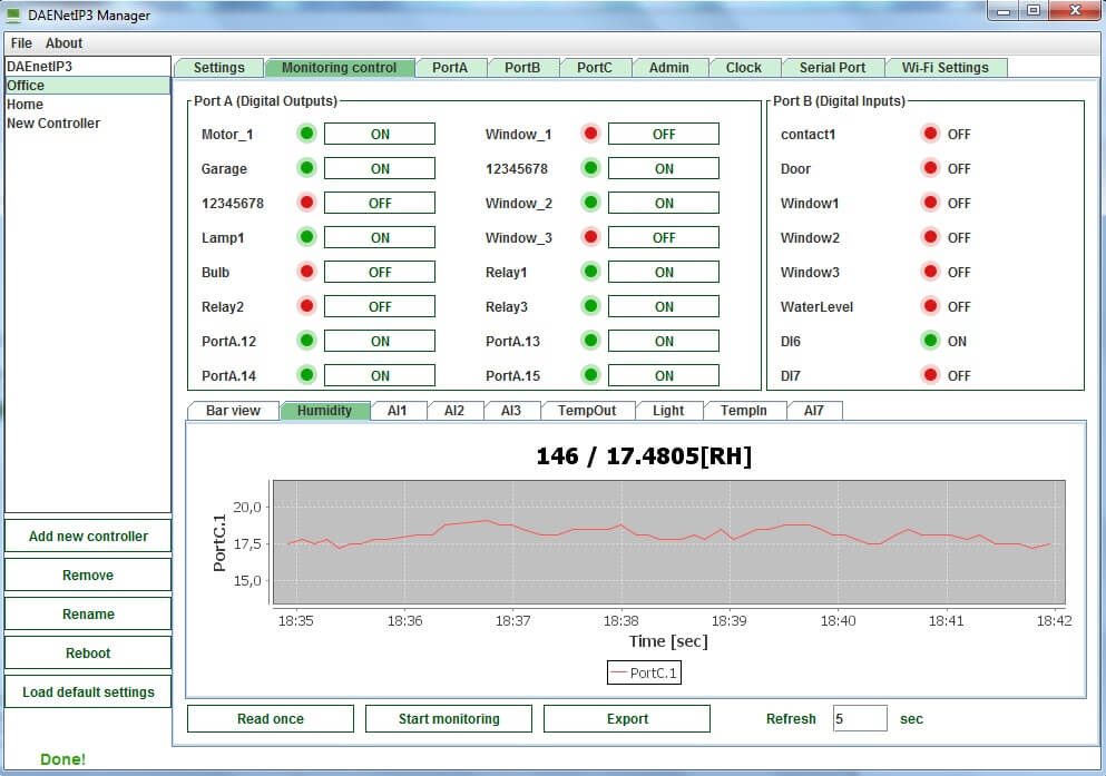
- Chart and log for every analog input almost in real time which can be exported in XML file later for further analysis;
- Easy copy settings from one DAEnetIP3 to another;
- Works on Windows, Linux, OS X.
- General overview
- Who can use DAEnetIP3 Manager ?
- List with currently supported DAEnetIP3 devices
- Current version download
- DAEnetIP3 Manager system requirements
- Settings
- Monitoring control
- Digital outputs port (Port A)
- Digital Inputs Port (Port B)
- Analog Inputs Port (Port C)
- Real Time Clock (RTC)
- UART (Serial Port)
- Wi-Fi 802.11 interface
DAEnetIP3 Manager is confirguration utility for all our DAEnetIP3 controllers and modules. Generally it duplicates all the features the DAEnetIP3 has over its web interface. The difference is that with DAEnetIP3 it is possible to access many controllers with single program and there are some additional useful functions, like charts, logging and easy migration of settings from one DAEnetIP3 to another.
The the ability to connect various sensors to the DAEnetIP3 modules plus this software, you can have very useful automation system which can monitor and log parameters like temperature, humidity, light... More information how to connect sensors to DAEnetIP3 you can find here:
http://denkovi.com/connecting-analog-sensors-to-daenetip3
http://denkovi.com/connecting-analog-sensors-to-DAEnetIP3-ethernet-12-relay-module
DAEnetIP3 Manager may be used by any customer who has at least one of DAEnetIP3 devices from the current version supported list.
List with currently supported DAEnetIP3 devices
|
Order number
|
Device name and link
|
| DAEnetIP3-Ex | DAEnetIP3-Ex |
| DAEnetIP3-Wx | DAEnetIP3-Wx |
| DAE-RB/Ro8-12V + DAEnetIP3-ET | DAEnetIP3 with 8 relay Board (Ethernet version) |
| DAE-RB/Ro8-12V + DAEnetIP3-WT | DAEnetIP3 with 8 relay Board (Ethernet version) |
| DAE-PB-RO12-JQC/DI8/AI8 + DAEnetIP3-EB | Ethernet 12 relay module - Web, TCP/IP, Telnet, HTTP API, E-mails |
| DAE-PB-RO12-JQC/DI8/AI8 + DAEnetIP3-WB | Wi-Fi 12 relay module - Web, TCP/IP, Telnet, HTTP API, E-mails |
|
Version
|
Release date
|
Windows download
|
Details
|
| 1.0 | 11 July 2014 |
NOTE: The DAEnetIP3Manager.jar file is located along with "lib" folder which contains the libraries for the software. This "lib" folder must be in the current directory of the DAEnetIP3Manager.jar file otherwsie it won't start. |
DAEnetIP3 Manager system requirements
- Operating systems: Windows, Linux, Mac
- Java Virtual Machine: Yes - required (Java 7)
- Required minumum DAEnetIP3 firmware version - 2.0.0 (if you would like to upgrade your firmware, please just send us email and we will send instructions).
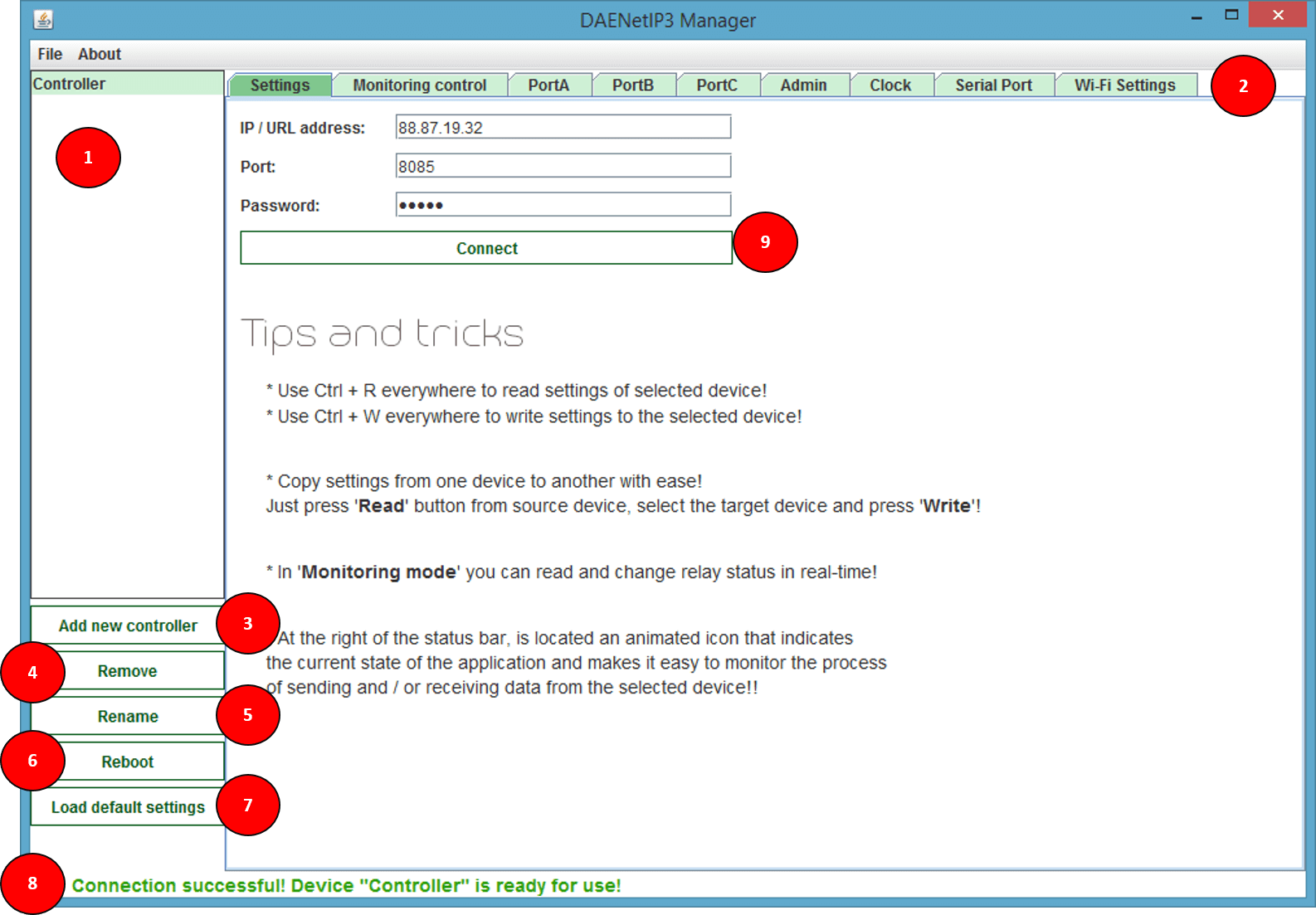
- 1 - Here are located all available DAEnetIP3 devices.
- 2 - DAEnetIP3 settings sections.
- 3 - Add new DAEnetIP3 device.
- 4 - Remove current DAEnetIP3 device.
- 5 - Rename current DAEnetIP3 device.
- 6 - Reboot current DAEnetIP3 device.
- 7 - Load default settings of selected device.
- 8 - Status bar which indicates the status (successful or not) of each command.
- 9 - This button just tests if there is connection with the target DAEnetIP3 device.
Parameters:
- IP address - the IP address (or DNS name) of the DAEnetIP3 device (by default it is 192.168.0.100).
- Port - the HTTP port of the target DAEnetIP3 device (by default it is 80).
- Password - the web password of selected device (by default it is admin).
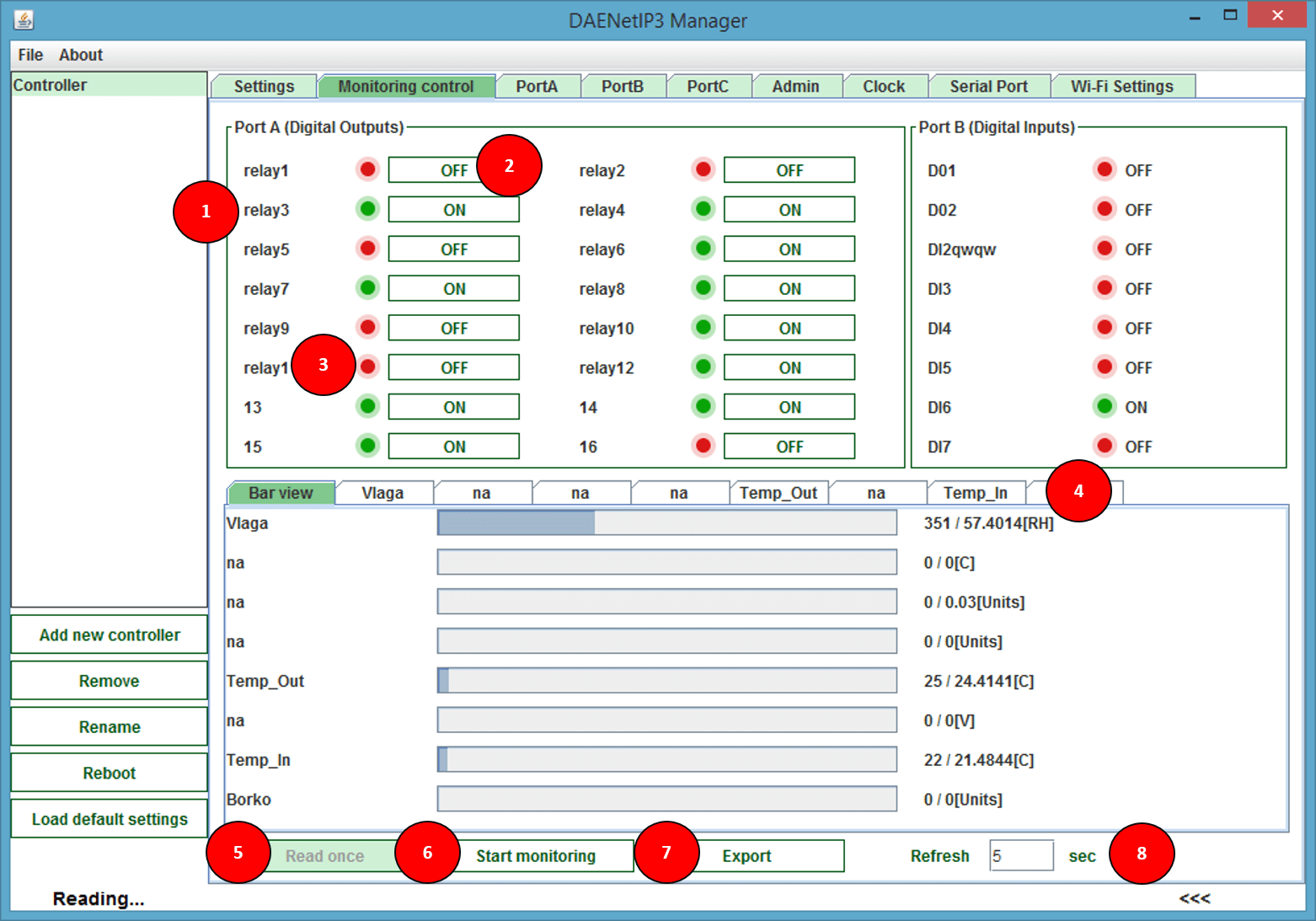
- 1 - I/O Port name.
- 2 - Real time Switch ON/OFF button (disabled in 'Monitoring Mode').
- 3 - Current I/O Port status.
- 4 - Analog inputs (PortC) panel. "Bar View" tab displays the ADC shownings like bars. The rest tabs show chart for every analog input channel.
- 5 - Executes 'Read' command once, which means read all the i/o once.
- 6 - Starts or stops real time monitoring/logging.
- 7 - Exports current device ports status to XML file.
- 8 - Determines how many seconds to wait before next try to execute the query (for monitoring).
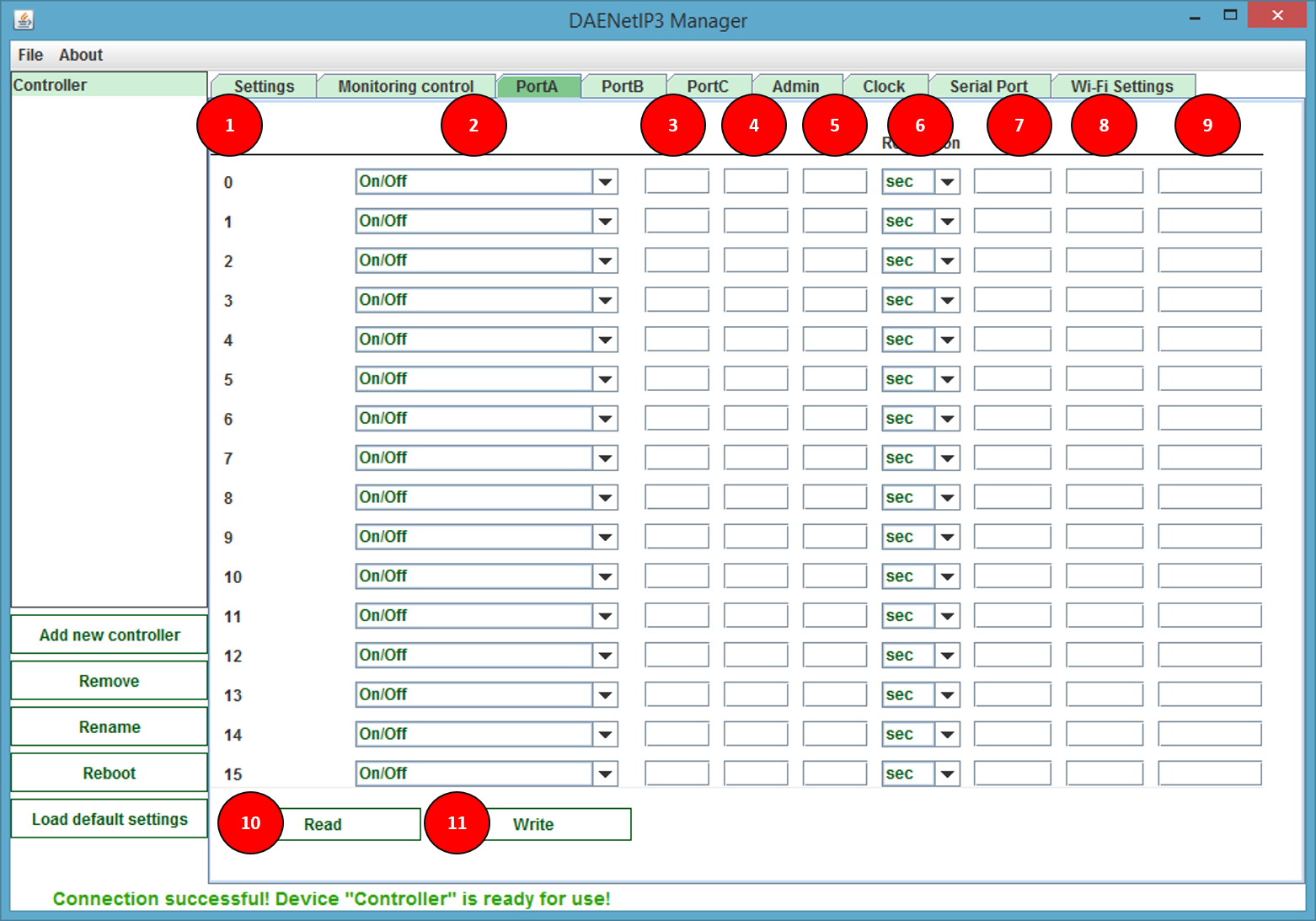
- 1 - Port A Pin numbers
- 2 - Port A modes
- 3 - This value is available for each digital output and determines the ON time (the time when the output is in high level) when the output works in some of the pulse modes. The ON value is >=1 and <=99.
- 4 - This value is available for each digital output and determines the OFF time (the time when the output is in low level) when the output works in some of the pulse modes. The OFF value is >=1 and <=99.
- 5 - This value is available for each digital output and determines the one shot pulse delay time when the output works in some of the timer modes. The Delay value is >=1 and <=99.
- 6 - This value is available for each digital output and determines if the ON, OFF and Delay values are in seconds, minutes or hours.
- 7 - This value is available for each digital output and determines the Time 1 moment when the output works in some of the schedule modes. The Time 1 value is with format hh:mm:ss
- 8 - This value is available for each digital output and determines the Time 2 moment when the output works in some of the schedule modes. The Time 2 value is with format hh:mm:ss
- 9 - Description text for each output. It can string with the following chars: 'a'-'z', 'A'-'Z', '0'-'9', '_' and '.'.
- 10 - Read Port A values
- 11 - Write Port A values
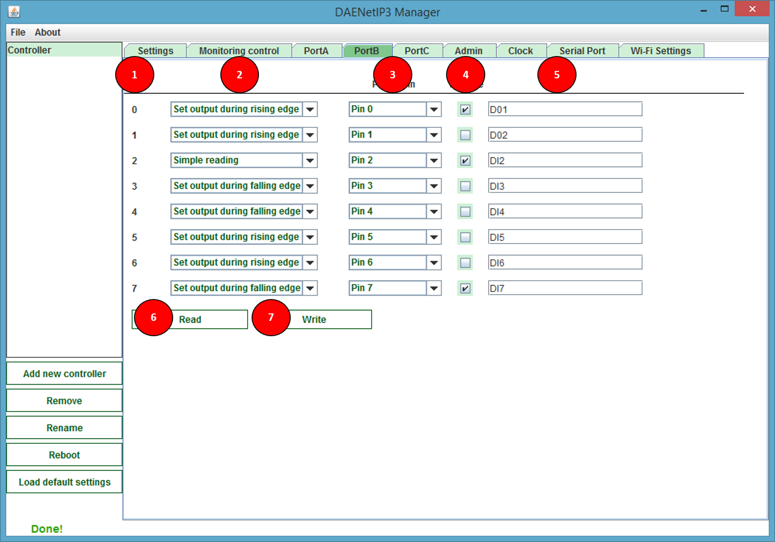
- 1 - Port B Pin numbers
- 2 - Port B modes
- 3 - This is abstract variable that is available for each digital input. It contains the number of some of the digital output lines. It determines which is the attached output line to this input. This means which output will react when this input detects falling/rising edge of the input signal.
- 4 - This boolean value (accept only true/false) is available for each digital inputs and determines if the digital output is of the current DAEnetIP3 controller or it is of another DAEnetIP3 controller in the network.
- 5 - Description text for each input. It can string with the following chars: 'a'-'z', 'A'-'Z', '0'-'9', '_' and '.'
- 6 - Read Port B values
- 7 - Write Port B values
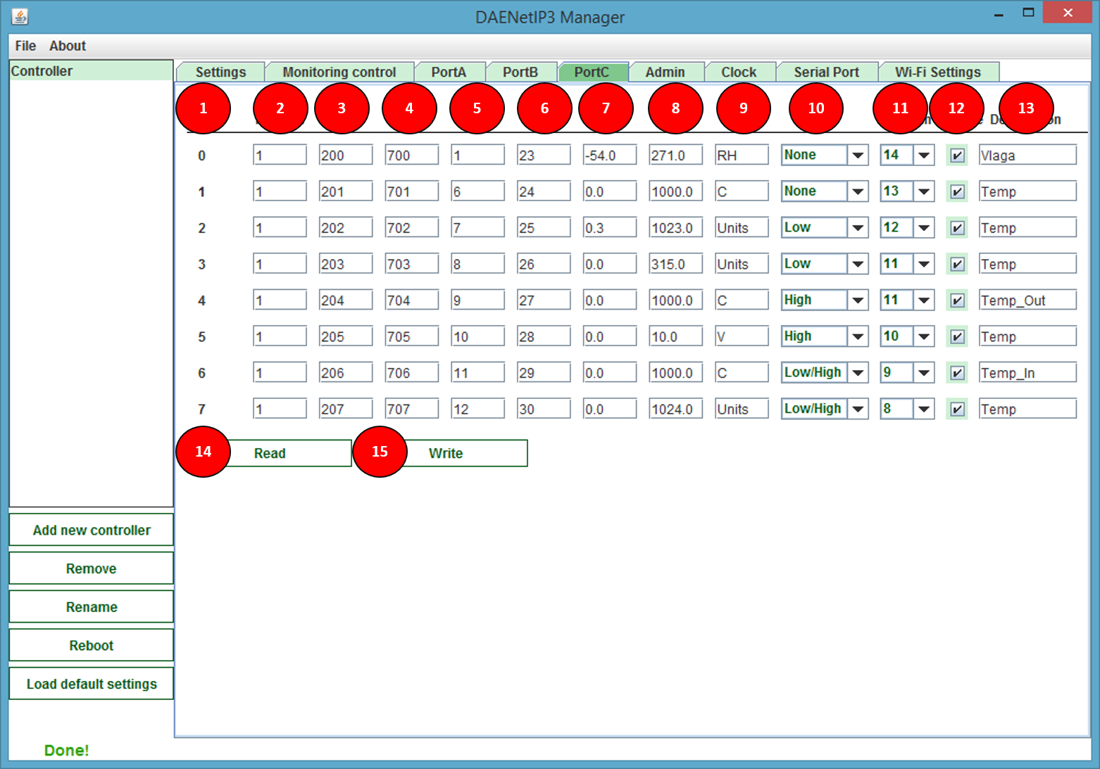
- 1 - Port C Pin numbers
- 2 - This is the period for reading (refreshing) the analog inputs. The minimum value is 1 (0.1s=100ms). The maximum is 99 (9.9ms=9900ms). The default value is 1.
- 3 - This is one of the thresholds (limits) that is used for events generating. The value is between 1 and 1023.
- 4 - This is the second threshold (limit) that is used for events generating. The value is between 1 and 1023.
- 5 - This value is the hysteresis for the Low Threshold. The value is between 1 and 512.
- 6 - This value is the hysteresis for the High Threshold. The value is between 1 and 512.
- 7 - This value is equal of ADC value = 0 divisions.
- 8 - This value is equal of ADC value = 1024 divisions.
- 9 - This is the label in which is measured the analog input. It may be "V", "C", "RH"...
- 10 - Analog Input Mode
- 11 - This is abstract variable that is available for each analog input. It contains the number of some of the digital output lines. It determines which is the attached output line to this input. This means which output will react when this input generates event.
- 12 - This boolean value (accept only true/false) is available for each analog inputs and determines if the digital output (given by “Remote” value) is of the current DAEnetIP3 controller or it is of another DAEnetIP3 controller in the network. If the value is “true” then the input controls another DAEnetIP3's digital output, otherwise (if “false”) it controls the current DAEnetIP3 digital output line.
- 13 - Description text for each input. It can string with the following chars: 'a'-'z', 'A'-'Z', '0'-'9', '_' and '.'.
- 14 - Read Port C values
- 15 - Write Port C values
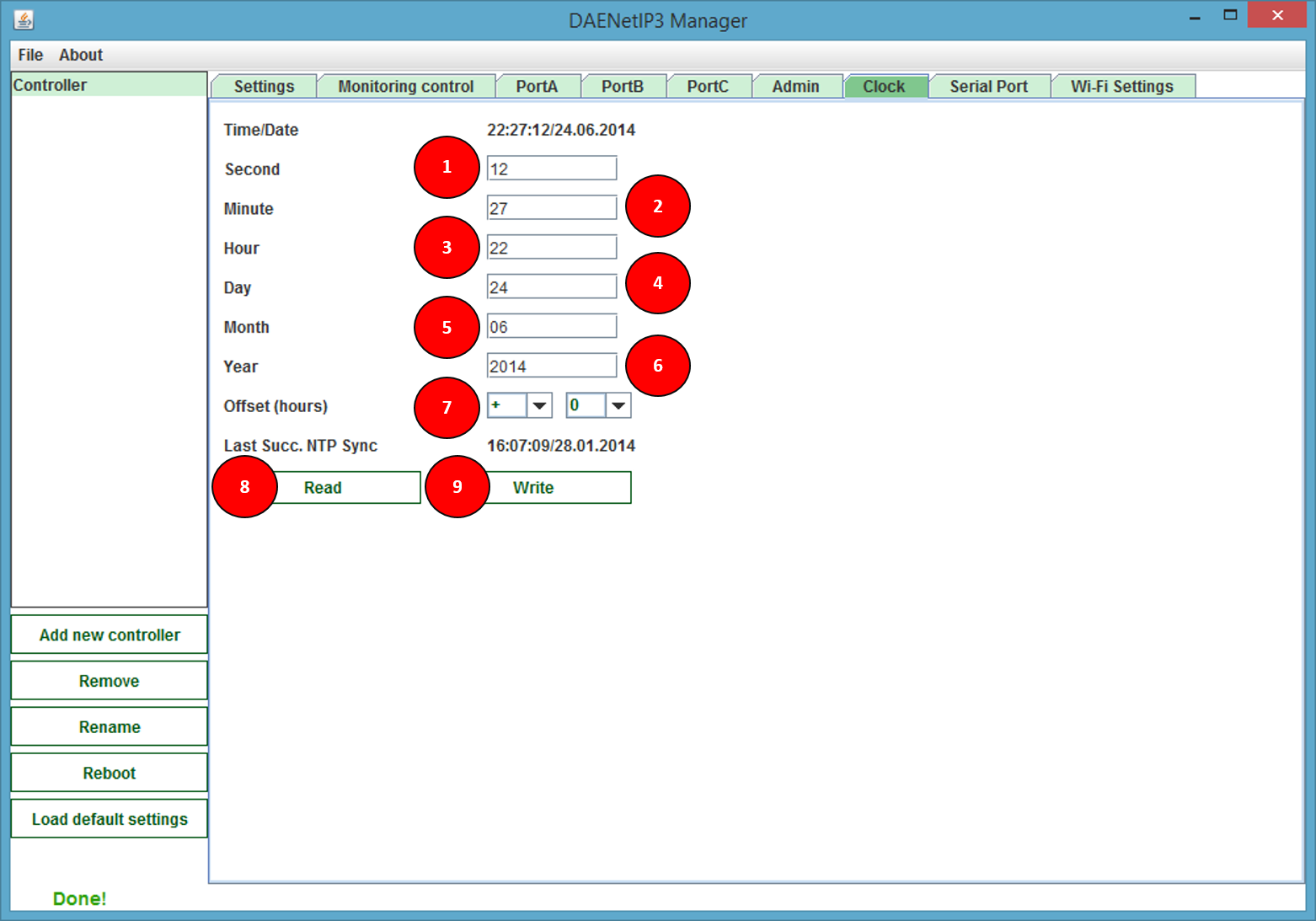
- 1 - Set current seconds
- 2 - Set current minutes
- 3 - Set current hours
- 4 - Set current day
- 5 - Set current month
- 6 - Set current year
- 7 - Determines the offset in hours applied to the date/time when it is synchronizing via NTP
- 8 - Read clock settings
- 9 - Write clock settings
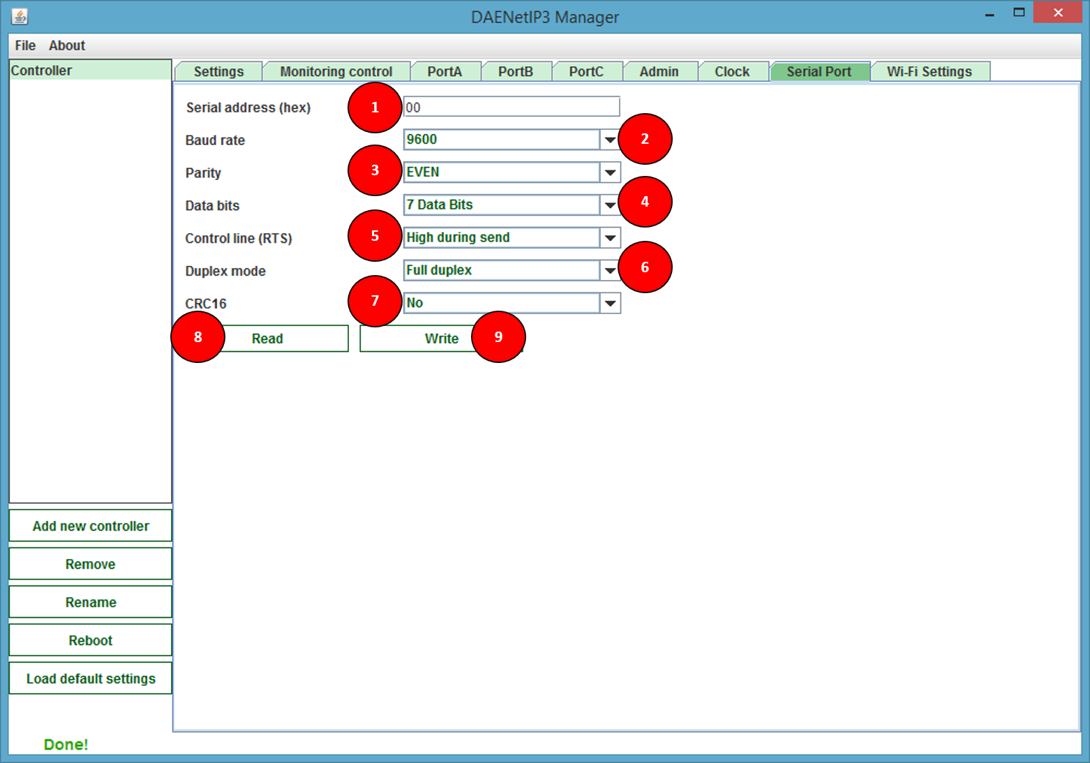
- 1 - Serial address. It may be from 00hex to FEhex (0dec - 254dec). This is the serial address of the controller in the serial network. The controller will respond on command that is only with its serial address. There shouldn't be duplicate serial addresses. The serial address FF is reserved and it can not be assigned to any DAEnetIP3 controller
- 2 - Baud rate. It may be 300, 600, 1200, 2400, 4800, 9600, 14400, 19200, 38400, 56000, 57600, 115200, 128000 or 256000.
- 3 - Parity. May be None,Even,Mark,Odd,Space.
- 4 - Data bits. 7 or 8.
- 5 - Control line. This is if the line is low during send or high during send.
- 6 - Duplex mode. Half-duplex (suitable for RS485) or Full-duplex.
- 7 - CRC16. If this parameter is enabled, then DAEnetIP3 UART port will sends (checks during receiving) CRC16 checksum of the data, appended to the end of the data and before the delimiter “;”. If this parameter is not enabled, then DAEnetIP3 will not sends (checks during receiving) CRC16 checksum.
- 8 - Read serial settings
- 9 - Write serial settings
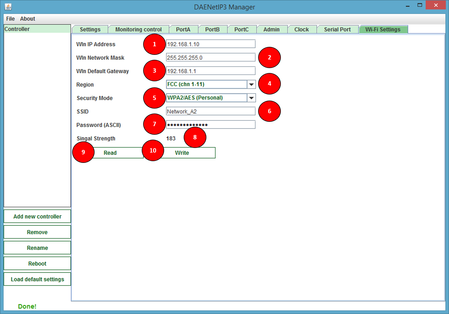
- 1 - Set the IP address of the module. This address is for the wireless interface.
- 2 - Set the mask of the module. This mask is for the wireless interface.
- 3 - Set the default gateway of the module. This gateway is for the wireless interface
- 4 - Set the region that is located the DAEnetIP3 controller.
- 5 - Set the Security Mode
- 6 - Set the name of the wireless network that the controller must be connected to.
- 7 - Set the WEP or WPA password
- 8 - Signal strength - Indication if the controller is associated to the wireless network and if yes, the signal level (from 0 up to 256 units)
- 9 - Read Wi-Fi settings
- 10 - Write Wi-Fi settings


