Cart is empty.
.png)


This page is about how to connect analog sensors to DAEnetIP3 ethernet 12 relay module. In this way it is possible to measure different analog values like temperature, humidity, distance and control electrical device or send e-mail based on the meausred values
- What is the purpose of this web page?
- For which devices is this tutorial?
- Hardware Revisions
- DAEnetIP3 ethernet relay module ADC port
- Connecting LM35DZ (temperature sensor)
- Connecting LM335 (temperature sensor)
- Connecting HIH-4000 (humidity sensor)
- Connecting GP2y0A21YK (distance sensor)
- Connecting TSL250R (light to voltage optical sensor)
What is the purpose of this web page?
This article main aim is to help you in projects where a various analog sensors must be connected to the inputs of our DAEnetIP3 ethernet 12 relay module and DAEnetIP3 WiFi 12 relay module. In most of the cases, these modules can work with analog sensors like LM35DZ (temperatre), HIH-4000 humidity and so on... Some of these sensors are with linear voltage output and some of them not. In the first case, their value can be easily calculated with single equation (linearization by 2 points) and this can be easily done in the browser. In the second case, however this is not possible with this method but still such sensors can be used for triggers(to switch relay, send email). Here, we've put some example schematics how to connect such sensor to these DAEnetIP3 modules.
We have created and small MS Excel file, which can help you to calculate tasks like:
- How to convert ADC units into sensor value (°C,m,%RH....). For example the browser showings of the ADC are in units (0-1023);
- How to convert sensor value into ADC units. For example when you want to set the low/high threshold but you know the sensor value is °C;
- Solve linearization by two points (which is required in software applications, where the ADC value can displayed directly in units like °C,m,%RH and so on); For example some applications require to enter sensor value in °C at 0 units and sensor value at 1024 unuts. This file will help you to solve them.
- Create custom software application showing ADC values in units like °C,m,%RH and so on;
For which devices is this tutorial ?
This tutorial may be useful for all customers that have the following devices:
|
Order number
|
Device name and link
|
| DAE-PB-RO12-12V/DI8/AI8 + DAEnetIP3-EB | Ethernet 12 relay module - Web, TCP/IP, Telnet, HTTP API, E-mails |
| DAE-PB-RO12-24V/DI8/AI8 + DAEnetIP3-EB | Ethernet 12 relay module - Web, TCP/IP, Telnet, HTTP API, E-mails |
| DAE-PB-RO12-12V/DI8/AI8 + DAEnetIP3-WB | Wi-Fi 12 relay module - Web, TCP/IP, Telnet, HTTP API, E-mails |
| DAE-PB-RO12-24V/DI8/AI8 + DAEnetIP3-WB | Wi-Fi 12 relay module - Web, TCP/IP, Telnet, HTTP API, E-mails |
| Date | Changes |
| 06 Nov 2017 |
Please note DAEnetIP3 controllers, produced after this date are with:
The R2 resistor shown on the below schematics is 270K instead of 300K. |
DAEnetIP3 ethernet relay module ADC port
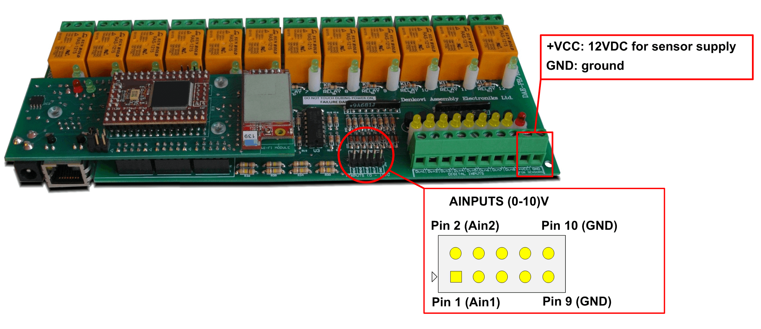
The sensor must be connected to the Ethernet Module ADC port which is under the name AINPUTS (0-10)V. Its location is marked on the image bellow.
For convience, this module has as well 12VDC output and ground for sensors (on the PCB this is +VCC and GND from the "FOR SENSOR" section next to the digital inputs as shown on the image bellow)
Below are listed example schematic connections for analog output sensors to DAEnetIP3 12 Relay Module
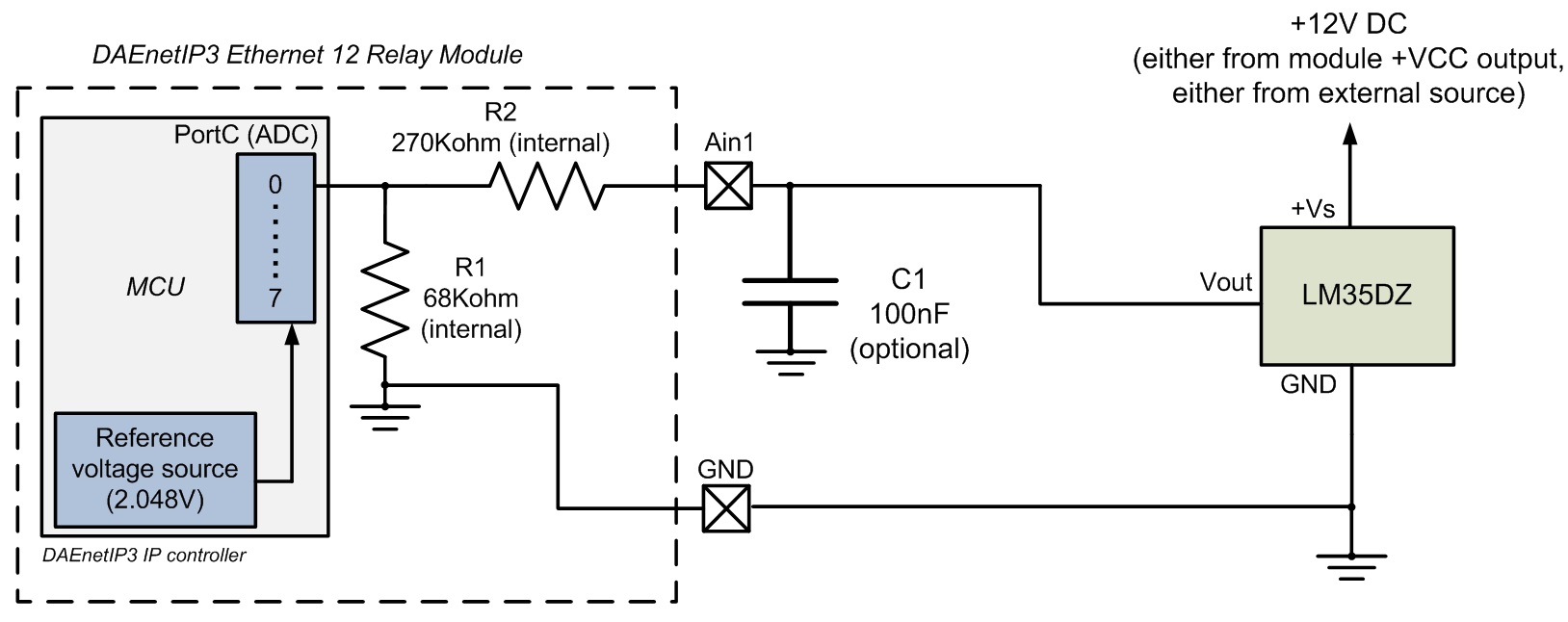
Connecting LM35DZ (temperature sensor) to DAEnetIP3 12 Relay Module
- LM35DZ can be bought from our webshop eas well - here.
- LM35DZ is temperature sensor with linear voltage output, which can measure temperatures from 0°C up to 100°C
 LM35DZ datasheet - here
- The schematic is tested with 20 meters flat cable and works well in our laboratory. However for more noisy environment and longer cabel, an extra measurements may be required which are not object of this example.
- The power supply 12VDC for LM35DZ may be taken either from the module (FOR SENSORS -> +VCC) either from external power source;
- The C1 capacitor is optional. It is recommend to be used if the sensor value is not constant.
- Settings for web browser (to show directly in °C degrees):

- Some data, which may help you:
|
Parameter
|
Value
|
Dimension | Note |
| ADCRes | 10 | bits | The resolution of the ADC |
| Vref | 2.048 | V | The referent voltage of the DAEnetIP3 controller |
| R1 | 68 | Kohm | It is built-in the module (see the above schematic) |
| R2 | 270 | Kohm | It is built-in the module (see the above schematic) |
| SensMin | 0 | °C | The minimum value of the sensor |
| SensMax | 100 | °C | The maximum value of the sensor |
| SensorRes | 0.01 | V / °C | Sensor resolution, it is taken from the sensor datasheet |
| Vtest | 100 | °C | Testpoint value |
| Vvalue | 1 | V | Output voltage during the testpoint (Vtest) |
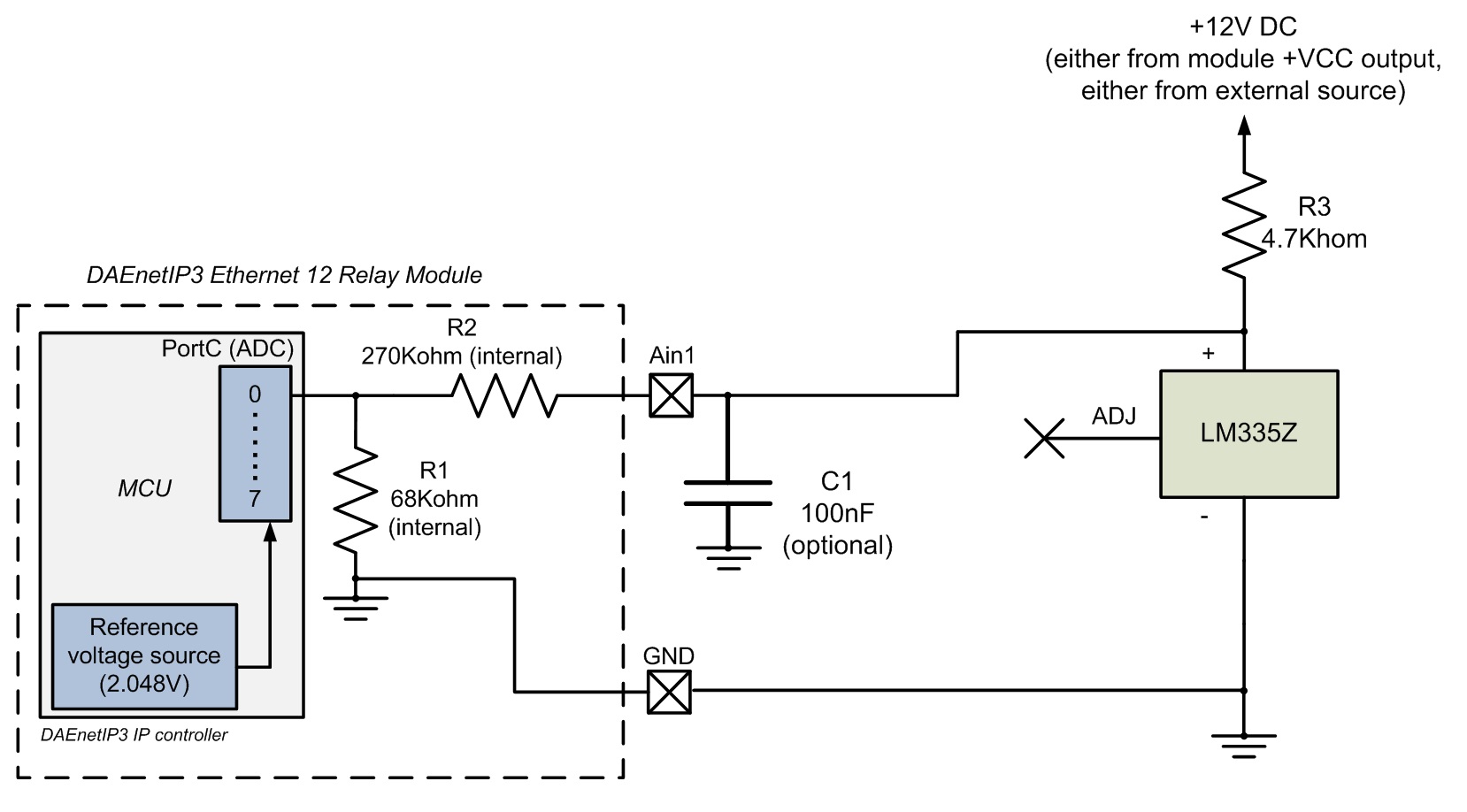
Connecting LM335Z (temperature sensor) to DAEnetIP3 12 Relay Module
- LM335Z can be bought from our webshop as well - here.
- LM335Z is temperature sensor with linear voltage output, which can measure temperatures from -40°C up to 100°C
- LM335Z datasheet - here
- The schematic is tested with 20 meters flat cable and works well in our laboratory. However for more noisy environment and longer cabel, an extra measurements may be required which are not object of this example.
- The power supply 12VDC for LM335Z may be taken either from DAEnetIP3 either from external power source.
- The C1 capacitor is optional. It is recommend to be used if the sensor value is not constant.
- Settings for web browser (to show directly in °C degrees):

Please note this is not so precise solution because here we have about 1 C degree per 1 ADC unit. For more precise solution you can connect several LM335Z sensors sequentially (please refer to the LM335Z datasheet). Or if you would like to customize your relay module to measure more precisely temperature with signle LM335Z, please contact us before purchasing.
- Some data, which may help you:
|
Parameter
|
Value
|
Dimension | Note |
| ADCRes | 10 | bits | The resolution of the ADC |
| Vref | 2.048 | V | The referent voltage of the DAEnetIP3 controller |
| R1 | 68 | Kohm | It is built-in the module (see the above schematic) |
| R2 | 270 | Kohm | It is built-in the module (see the above schematic) |
| SensMin | -40 | °C | The minimum value of the sensor |
| SensMax | 100 | °C | The maximum value of the sensor |
| SensorRes | 0.01 | V / °C | Sensor resolution, it is taken from the sensor datasheet |
| Vtest | 25 | °C | Testpoint value |
| Vvalue | 2.98 | V | Output voltage during the testpoint (Vtest) |
- The other sensors from this sieries are LM235 and LM135 - they can also be connected to the DAEnetIP3 12 Rwlay Module the same way, however please refer to their specification.
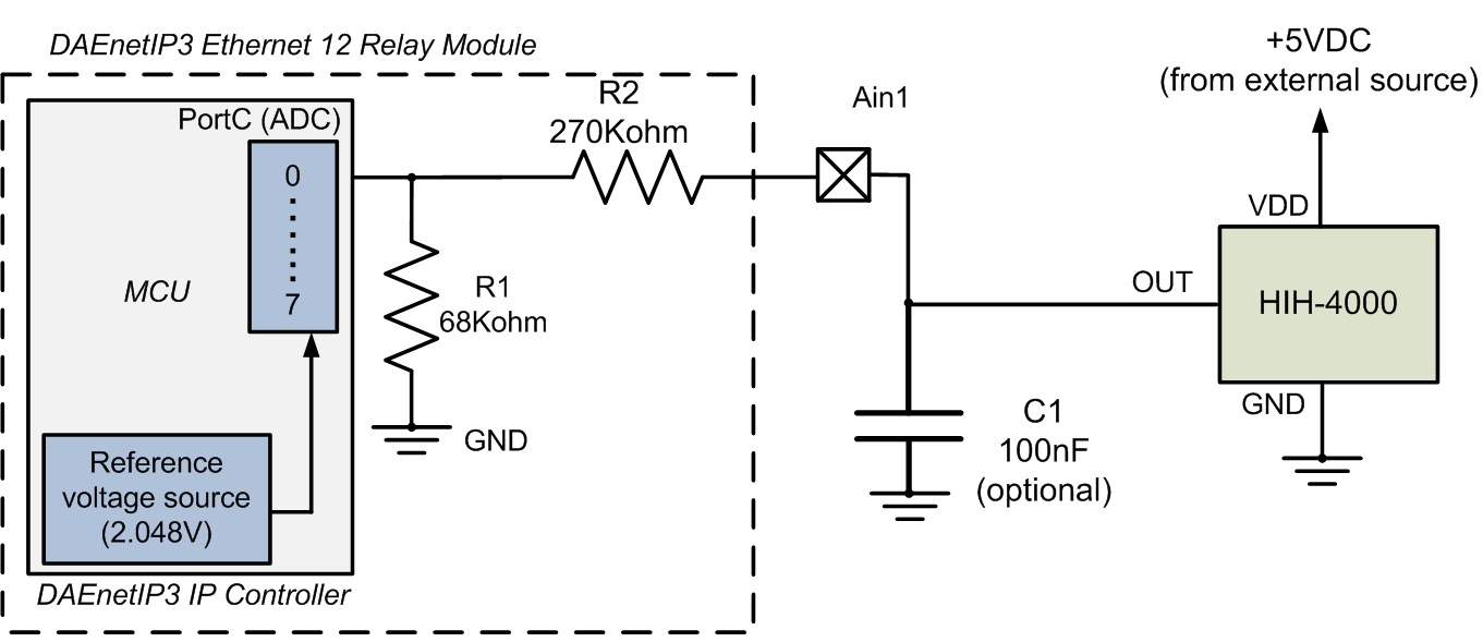
Connecting HIH-4000 (humidity sensor) to DAEnetIP3 12 Relay Module
- HIH-4000 can be bought from our webshop as well - here
- HIH-4000 is humidity sensor with almost linear voltage output which can measure humidity from 0%RH upto 100%RH.
- HIH-4000 datasheet - here.
- The schematic is tested with 20 meters flat cable and works well in our laboratory. However for more noisy environment and longer cabel, an extra measurements may be required which are not object of this example.
- The power supply 5VDC for HIH-4000 must be taken from external power source only.
- The C1 capacitor is optional. It is recommend to be used if the sensor value is not constant.
- Settings for web browser (to show directly in %RH): "Analog Inputs" -> Max = 302.00, Min = -28.00, Label = RH
- Some data, which may help you:
|
Parameter
|
Value
|
Dimension | Note |
| ADCRes | 10 | bits | The resolution of the ADC |
| Vref | 2.048 | V | The referent voltage of the DAEnetIP3 controller |
| R1 | 68 | Kohm | It is built-in the module (see the above schematic) |
| R2 | 270 | Kohm | It is built-in the module (see the above schematic) |
| SensMin | 0 | %RH | The minimum value of the sensor |
| SensMax | 100 | %RH | The maximum value of the sensor |
| SensorRes | 0.03068 | V / %RH | Sensor resolution, it is taken from the sensor datasheet |
| Vtest | 75.3 | %RH | Testpoint value |
| Vvalue | 3.198 | V | Output voltage during the testpoint (Vtest) |
Connecting GP2Y0A21YK (distance sensor) to DAEnetIP3 12 Relay Module
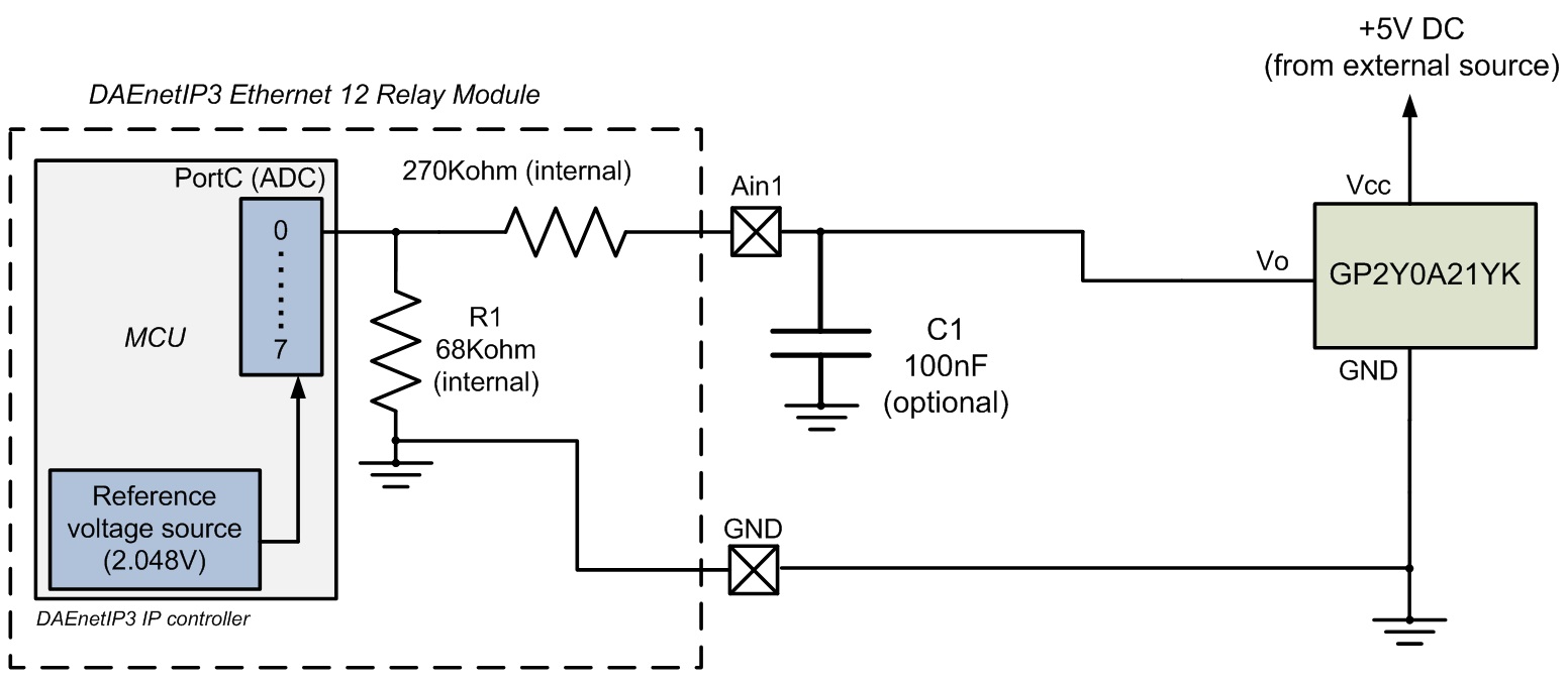
- GP2Y0A21YK can be bought from our webshop as well - here
- GP2Y0A21YK is infrared proximity sensor with non-linearity voltage output but it can still be used for triggering (to activate relay or send email).
- GP2Y0A21YK datasheet - here
- The schematic is tested with 20 meters flat cable and works well in our laboratory. However for more noisy environment and longer cabel, an extra measurements may be required which are not object of this example.
- The power supply 5VDC for GP2Y0A21YK must be taken from external power source;
- The C1 capacitor is optional. It is recommend to be used if the sensor value is not constant;
- The R1 and R2 resistors are is built in the module, so you don't have to connect them
- You can use and the other Sharp sensor 20-150cm sensor the same way - http://denkovi.com/infrared-proximity-sensor-20-150cm
Connecting TSL250R (light to voltage optical sensor) to DAEnetIP3 12 Relay Module
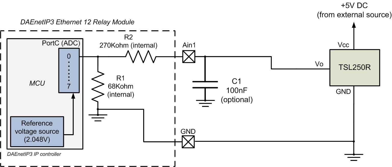
- TSL250R can be bought from our webshop as well - here
- TSL250R is light to voltage optical sensor with non-linearity voltage output but it can still be used for trigger (to activate relay or send email).
- TSL250R datasheet - here
- The schematic is tested with 20 meters flat cable and works well in our laboratory. However for more noisy environment and longer cabel, an extra measurements may be required which are not object of this example.
- The power supply 5VDC for TSL250R must be taken from external power source;
- The C1 capacitor is optional. It is recommend to be used if the sensor value is not constant.
- The R1 and R2 resistors are is built in the module, so you don't have to connect them
- The other sensors from this sieries are TSL251R and TSL252R - they can also be used with DAEnetIP3 12 Relay Module the same way, however please refer to their specification


