Cart is empty.
.png)


Denkovi Relay Manager (DRM) is windows/linux software for easy controlling all kinds of Denkovi relay boards (USB,SNMP,TCP/IP). It is software for controlling only the relays of denkovi modules.
|
|
- General overview
- What can DRM Software do
- Who can use DRM Sofware
- List with currently supported relay boards
- Current version download
- DRM Software system requirements
- DRM installation guide for Windows
- DRM installation guide for Linux
- User interface
- Control mode
- Timer mode
- Weekly mode
- Calendar mode
- Pulse mode
- Settings
- Relay status
- Troubleshooting
With DRM software and our low cost but high quality relay boards, you may turn your desktop machine or notebook in powerfull automation system without need of programming. USB, VCP, SNMP or IP relay board interface - it doesn't matter, the application will turn any relay from any relay board when you want and in the way you like. Turn the relays manually, adjust them to be turned on/off at particluar time each day, or only during the weekend, or simply 'tell' them to be 1 secound ON and 5 seconds OFF...only with several clicks! All of these functions can be adjusted for each relay channel separately.
DRM software is universal application for controling all the Denkovi relay boards. It is based on our previous similar applications and some customers' requests. It includes many features that other companies offers for lot of money.
DRM is universal relay manager that allows you to control up to 32 relay boards from a single running application - it doesn't matter what kind is the Denkovi relay board you have.
The main purpouse of DRM software is saving your money and time. It also brings you great possibilites that allow to create basic algorithms for automation with our relay boards without any programming skills.
If you have any ideas for future versions or you would like to modify the software for your needs, please feel free to contact with us and we will help you.
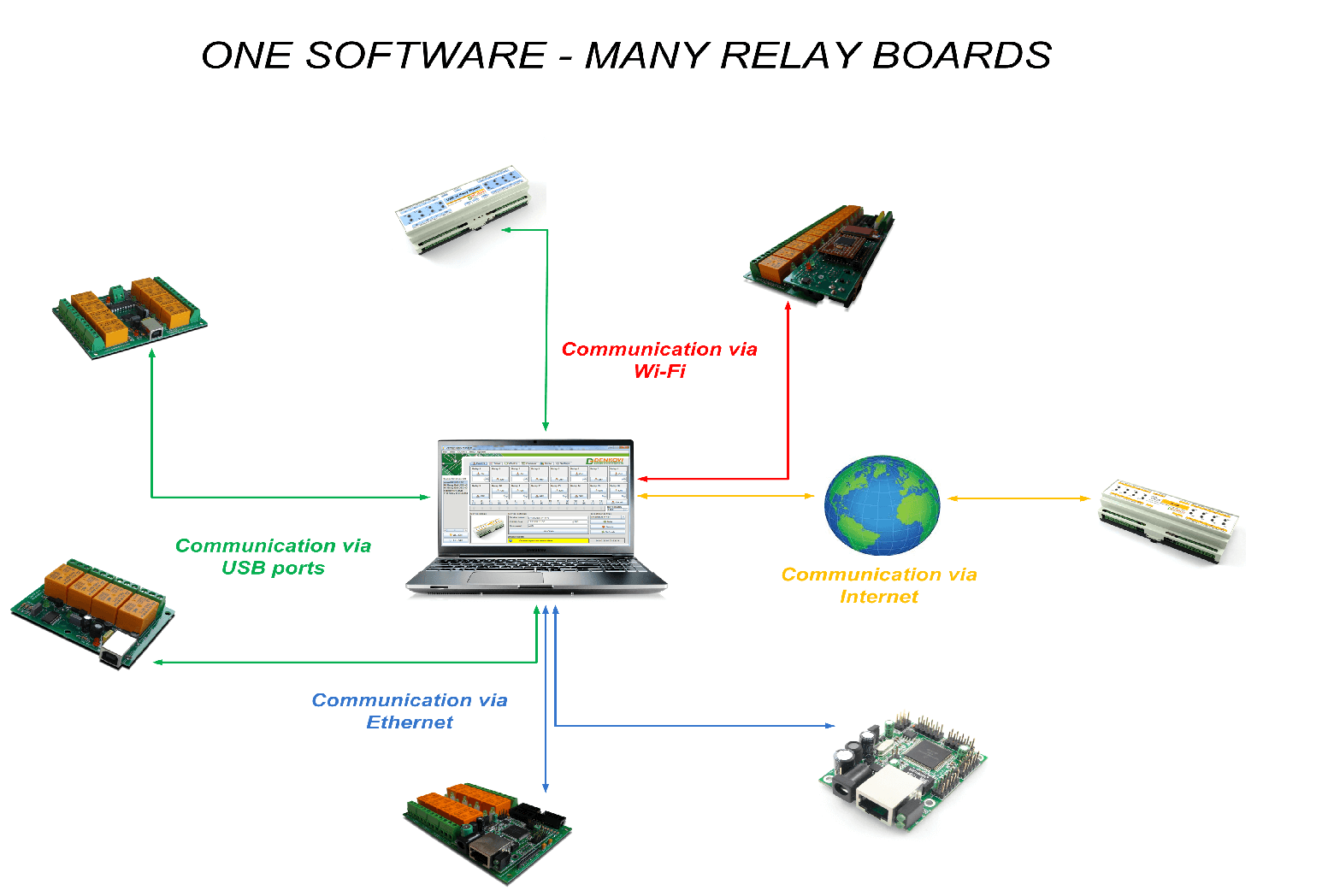
Whit DRM Software you may control up to 32 Denkovi relay boards from one PC. You may easily set four different modes for each relay independently from each relay board. It doesn't matter the communication protocol or how many relay channels has the relay board. The image below shows example configuration with single PC (with DRM Software), router and 6 Denkovi relay boards. This is an example how you may control 64 relay channels.
Basicly there are five working modes for each relay channel. Each relay may work in only one mode each moment. For example 3 of your relays may be controled direclty by you, 5 may work in timer mode, 2 relays may be turned only on monday, 4 may be turned at specific date and time and the rest may work in pulses (1 sec ON and 2 sec OFF for example). This is special feature of the software that allows you to be more flexible. The possible relay modes are:
1. Control Mode. In this mode you can simply set the relays or make single pulses. You may set ON/OFF single relay or you may set all the relays in specific state as you want. For example we set Relay 1 ON or Relay 1,2,3,4 ON and 5,6,7,8 OFF at once. For more detailed information [Control Mode]
2. Timer Mode. This mode is based on our previous USB Timer applications. By this mode you can give different states, sequences and delays for each relay. For more detailed information [Timer Mode]
3. Weekly Mode. This is mode for turning ON/OFF the relay according days of the week. Each relay may be turned ON and turned OFF once per day. You may select which days of the week this relay to be turned. For example we set: On Saturday and Sunday set Relay 3 ON at 11:00:00 and OFF at 13:00:00. For more detailed information [Weekly Mode]
4. Calendar Mode. This modeis combination of the previous two. You create sequences of events for each relay - event list. Each event has date, time and relay state. For example we set the following event: On 12.12.2011 at 10:22:15 set Relay 1 ON or During weekends at 10:22:15 set Relay 2 OFF. For more detailed information [Calendar Mode]
5. Pulse Mode. This mode makes the relay cyclic to be ON and OFF for specific time. For example we set the following: Set Relay 16 ON for 100 ms and OFF for 500 ms. For more detailed information [Pulse Mode]
DRM software may be used by anyone who has at least one of Denkovi relay boards from the current version supported list.
It is not allowed to use DRM software with relay boards which are not manufactured by Denkovi Assembly Electronics LTD. In order to check that, the software may need internet connection to verify your board the first time it is connected to specific user account in particular OS!
Denkovi customers who made orders before the release date of ver.2.0 may not be able to use versions 2.0 or greather immediately. Please contact with us with your order # and we will send you license for using DRM software 2.0 (or greather).
If you are our customer (you have ordered at least one relay board from us) but you have problems running the software with some relay board, please contact with us (sending us your invoice number) and we will assist you.
Please read this page for more information abour DRM software policy.
List with currently supported Denkovi relay boards
|
Version
|
Release date
|
Windows
|
Linux |
| 2.9.4 | 04.03.2021 | ||
| 2.9.3 | 12.03.2019 | ||
| 2.7 | 19.10.2016 |
|
|
| 2.6 | 17.06.2016 |
|
|
| 2.5 | 08.12.2015 |
|
|
| 2.4.1 | 03.01.2015 |
|
|
| 2.4 | 10.10.2014 |
|
|
| 2.0 | 03.06.2013 | ||
Version history may be downloaded from here
For older versions - please contact with us!
DRM Software system requirements
Operating systems:
- Windows (tested on Windows XP, Windows Vista, Windows 7 and Windows 8, Windows 10)
- Linux (tested on Ububtu and OpenSuse)
- Raspberry PI
Minimal screen size: 1024 x 768
Minimal CPU: 1GHz
Requires Java Virtual Machine: For Windows OS the last version is included from the release date in the installation .exe setup file. For Linux OS, please refer to Java site for instructions how to install the drivers.
Requires FTDI drivers: For Windows OS, they are included in the installation setup file. For Linux OS the FTDI drivers are built in the kernel.
DRM Installation guide for Windows
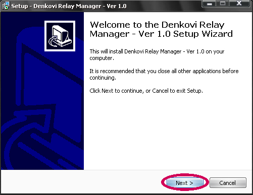
To get installed DRM software on your PC the only thing you need to do is to download and run the installation file DRMsetup.exe. The whole installation takes several minutes. Here are the steps you should go through the installation:
1) Download DRMsetup.exe and run it.
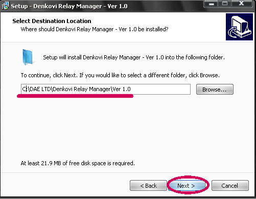
2) Select the place you would like to be installed DRM software. It is recommend to install it on drive that is different from C:\
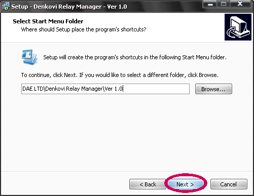
3) Setup will create icons on your start menu.
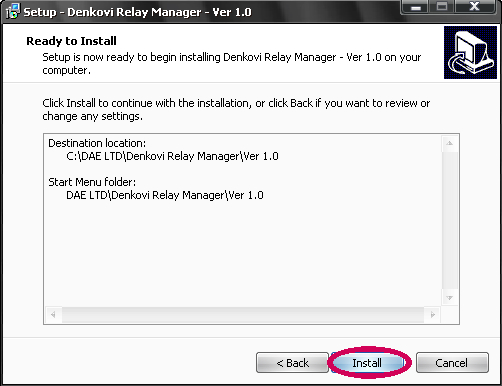
4) Install.
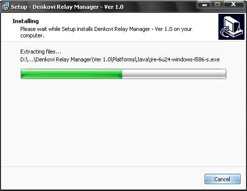
5) Installation progress.
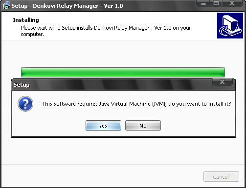
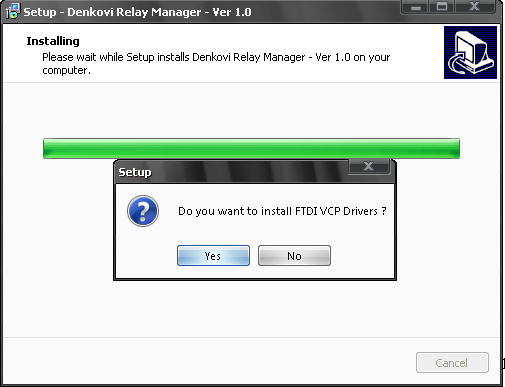
6) You will be asked if you have JVM (Java Virtual Machine). If your PC does not have any JVM installed, you need to click "Yes" and follow the steps that JVM installation window will guide throug. If you have already JVM click "No". If you have already JVM and click "Yes" to install it - don't worry. Nothing will be wrong, just will take several more minutes to update your JVM to the latest version.
7) You will be asked if you have all the necessary drivers installed. If you hve already FTDI VCP drivers on your PC, skip this step. Otherwise click "Yes".
8) Finish the installation.
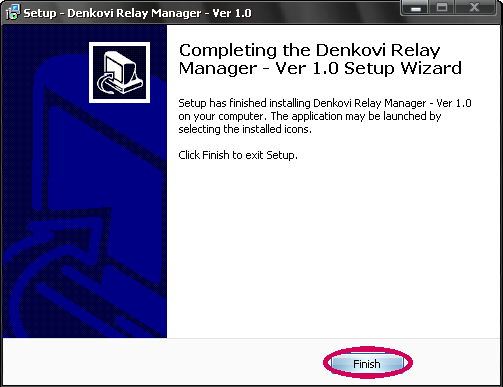
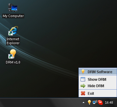
9) You may find the DRM icon on your desktop. Also there will be a try icon for show/hide DRM application when start it.
DRM Installation guide for Linux
We assume you have java virtual machine installed on your linux machine. The only you have to do is to unarchive the installation files.
In some Linux distributions, to run the software with click you have to set the .jar file to be executable.
.jpg)
You can also run it via command line with java -jar command:

Important !
In most Linux OS in order to run our USB relay boards (based on FTDI chipset) you must do the following each time when you connect such relay board: you must unload this driver (and usbserial) if it is attached to your device ("rmmod ftdi_sio" and "rmmod usbserial" as root user). After that the USB relay board(s) will be shown at the device list in DRM software.
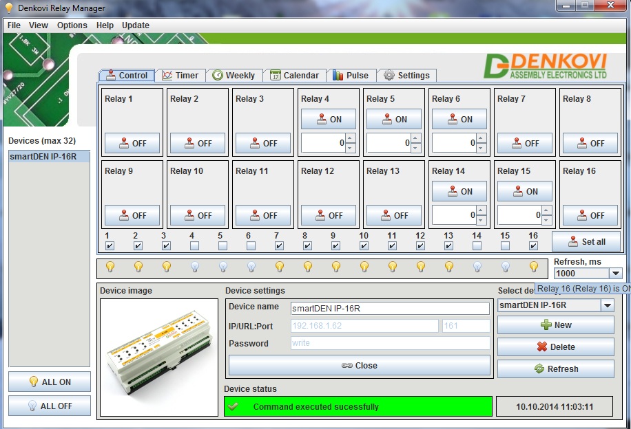
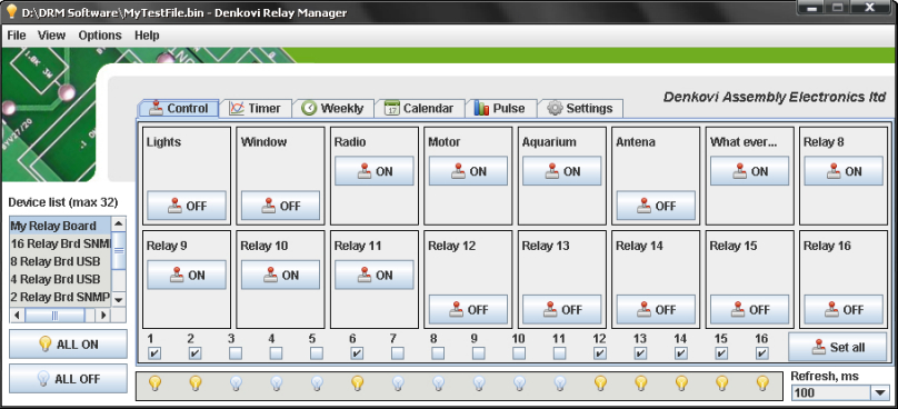
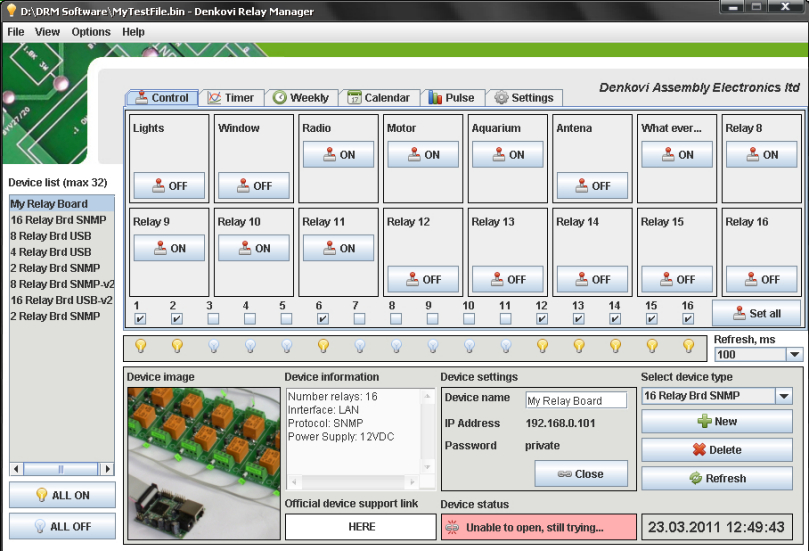
DRM has user-friendly graphical interface (GUI) and allows you to implement, save and load your automation algorithms very easy. It is possible to controll each relay of each connected relay board anytime.
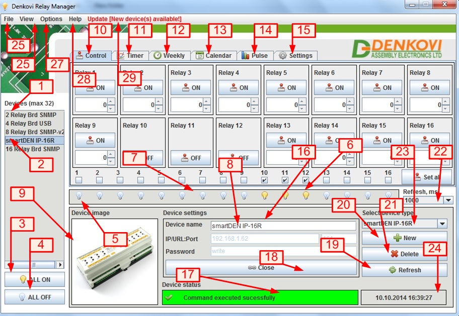
1) Device list. It contains all opened relay boards. Each relay board is shown with its name which may be set by the field "Device name" (22).
2) Opened relay board. This is one of the opened relay boards. If this relay board is selected, the program will display it.
3) Button 'ALL ON'. It turns ON all the relays from the selected relay board and it doesn't matter what is the relay mode.
4) Button 'ALL OFF'. It turns OFF all the relays from the selected relay board and it doesn't matter what is the relay mode.
5) Relay status indicator. It shows this relay is currently set ON, i.e. opened. In this case this is relay # 1.
6) Relay status indicator. It shows this relay is currently set OFF, i.e. closed. In this case this is relay # 3.
7) Indicator panel. It shows all the relay status indicators. For example if the number relays of currently selected relay board is 16, there will be 16 indicators in this panel.
8) Device information field. It shows basic information for currently opened relay board - number relays, interface type, used communication protocol and power supply.
9) Official support link. This is link for relay board detailed information. Also the relay board may bought from this link also.
10) Device image. It shows how does the relay board looks like. It is good wat to see what other relay boards are supported by this software.
11) Control mode tab.
12) Timer mode tab.
13) Weekly mode tab.
14) Calendar mode tab.
15) Pulse mode tab.
16) Settings tab.
17) Device settings panel. This panel contains all settings fileds that must be filled for correct communication with the relay board. When the relay board is 'opened' or is 'opening', then some of these fileds are disabled for changing. The current version contains 3 types of Device settings panel:
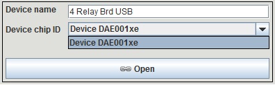
17.1) Settings panel for FIFO relay boards. Before opening some FIFO relay board it is necessary only to select which is the device you want to control. The device are listed by their serial numbers. If there is not devices connected to the PC, the list will be ampty nd if you then press button 'Open' a message for empty list will appear. Not that refreshing of the list is not automatically and it is done by pressing button 'Refresh' (21). If you already refreshed the list but for some reason the relay board in the list is unplugged, its chip ID wont be removed automatically and it if you try to open it or change its relays, the satus for unsucessfull connection will appear (18.5)
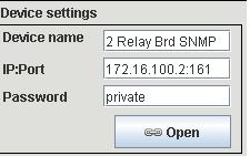
17.2) Settings panel for SNMP relay boards. Before opening some snmp relay board it is necessary to type the IP address, port and snmp community (Password). Usually the Port is 161 (by default) but sometimes it may be another. The IP and port are separated with : - for example: 172.16.100.2:161
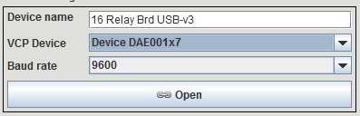
17.3) Settings panel for VCP relay boards. Denkovi VCP relay boards are relay boards that are connected to the PC via USB, but the communcation is serial. So to communicate with such relay board it is enogh to selectd its VCP device chip IP and the communcation baudrate. Usually the baude rate is 9600, but we had old versions of our popular USB 16 channel relay boards that works with 14400.
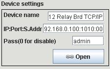
17.4) Settings panel for TCP/IP relay boards. Before opening some TCP/IP relay board it is necessary to type the IP address, port and serial address and password. The most imortant here is that with one IP:port you may access many serially connected devices with DRM. That is why we addedd the serial address. IP, Port and Serial address are separated with ":". For example: 192.168.0.100:1010:00. The password is used for RC4 encryption. If there is no password use just 0.
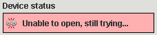
18) Device status panel. It shows what is the status connection of each relay board in the device list.There is five statuses:
18.1) Status for sucessfully opened device. This means that the device is connected to the PC and it is ready for work. This status is appeared when the Open button is pressed or, the application managed to reopen the device.
18.2) Status for sucessfully closed device. This means that the device is disconnected to the PC. This is automatically done also after closing the application.
18.3) Status for sucessfully executed command. This means that the relays are set sucessfully. There is not problem with relay board communication and all the relays are in states as in the application.
18.4) Status for unopened device. This means that you've tried to set the relays when the relay board is not 'opened' or 'opening' at the moment. The status message 'tells' you that you should 'open' the device first and then if the connection is sucsessfull you will be able to set ON/OFF the relays of this device (relay board).
18.5) Status for unsucessful connection and still trying to connect. This status may be said also "connecting...". This message appreas when the user trys to open some relay board, but there is problem with the communication. For example - cable is unplugged. In this case the application during some interval of time tries to connect automatically with the relay board. If the connection is sucsessful, status 18.1) will appear, otherwise there will be no change in the status - i.e. the status for unsucessful connection will remain.
19) Button 'Open/Close' relay board. This button open/close (connect/disconnect) the selected relay board.
20) Text field 'Device name'. It is for giving name of each relay board. This name is diplayed in the device list(1). There are may be many relay boards with the same name. There can not be relay board with empty name string. Because of this software feature it is very easy to know your relay boards.
21) Button 'Refresh'. It is for refreshing the device settings panel (17). The refreshing is not done automatically because it takes several seconds and it is good to be done only by usre's reqwest.
22) Button 'New'. It add new relay board to the device list.
23) Button 'Delete'. Deletes the selected relay board from the device list.
24) Combo box 'Refresh'. The possible choices are 100,200,300,400,500,600,700,800,900 and 1000 ms. This parameter sets the refresh time for the application. It depends on what kind of relay board do you use and what is the communication latency. For example if you use VCP relay board, this parameter may be 100ms because the communication is fast. But if you use some SNMP relay board and especially it is controlled by internet, the latency may be bigger and there may be delays, so you need to make this parameter bigger for example 1000ms. If you use for example 100ms it also will work, but in some cases relay board won't be changed so fast as the DRM software is set.
This is also the delay in ms for each delay unit in the application for the Timer mode and Pusle mode.25) Device type. It shows the currently selected relay board type. This list represents the list with currently supported relay boards. It serves also for setting the type for new relay board. Note that if a relay board is opened once, its type can not be chnaged. You will need to open another one. and delete this one for change the type.
26) Current date and time. It shows the current date and time at the moment according system clock.
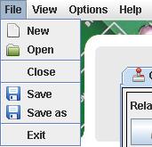
27) Menu 'File'. DRM software have feature to save/open files with the current relay boards, their settings and relays states. It contains the following sub menu items:
27.1) New. Click 'New' if you want to create blank new file.
27.2) Open. Click 'Open' if you want to open existing file.
27.3) Close. Click 'Close' if you want to close the current file.
27.4) Save. Click 'Save' if you want to save the currently opened file.
27.5) Save as. Click 'Save as' if you want to save the current file with some other name.
27.6) Exit. Click 'Exit' if you want to exit from the DRM software.
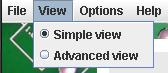
28) Menu 'View'.
28.1) Simple view. This view may be used when you've opened the boards and you need only simply to control them, whout any configurations.
28.2) Advanced view. It shown everithing. This is the default view when you start DRM for first time.
29) Menu 'Options'.
29.1) Start application on system boot. When this is checked then Auto start function is enabled and when the OS is started, the DRM is also started automaticaly. Note that if there is antivirus or firewall program started on your computer, it may be not possible to use this function. You need to turn off your antivirus/firewall program. This option is not available in Windows 8 and Linux for now.29.2) Load last file on start application. When this is checked then Auto load function is enabled and when the DRM software is started the last file will be loaded automatically.
29.3) Try to connect when file is loaded. When this is checked then Auto connect function is enabled and when some file is loaded if some of the relay boards in this file was previously in states 18.1,18.2,18.3 or 18.5 the DRM software will try to open this relay board automatically.
29.4) Set/Get the relays on connect. When this is checked then Auto set function is enabled and when DRM open some relay board it will set the relays as they are set by the DRM interface. If this is not set, the DRM will read and synchronize the relays states when it is connected to the board for first time. Please note that when the relay board is disconnected during DRM works and after that connected, the relays will be set (not get) without matter what is this setting.
29.5) Determines if ON/OFF 2 events in the week mode to be used.
If the four functions are enabled DRM has the special feature to continue running from last save point when the PC is booted.
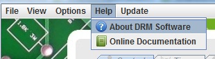
30) Menu 'Help'. Opens a window that contains support, contacts and current version information.
.jpg)
[back to top]
This is mode for simply turn ON/OFF the relays.
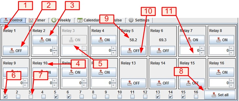
1) Relay name. This is the name for each relay. By default it is 'Relay 1' in this case. It may be changed by the user anytime.
2) Control relay button 'OFF'. When click this button the relay is turned OFF.
3) Control relay button 'ON'. When click this button the relay is turned ON.
4) Tooltip text. It is displayed when you hold the cursor over some graphical component to see more detailed information for it.
5) Relay button 'ON' (disabled). This button is disabled because this relay works in another mode.
6) Checkbox. If this checkbox is set (checked) when button 'Set all' is pressed this relay will be set ON, otherwise OFF.
7) Checkbox (disabled). It is disabled because this relay works in another mode.
8) Button 'Set all'. When this button is pressed all the relays are set at once according the state given by the checkboxes. If some checkbox is disabled, this relay won't be affected because it works in another mode.
9) Single Pulse Counter. Displays how many seconds remains until the relay is switched off automaticaly.
10) Button in control mode with set pulse counter. When this button is turned on, it will turned off automaticaly when the time elapes.
11) Pulse width field. Form this field you can adjust the pusl witdh (after what time the button will be turned off back).
By this mode you can give different states, sequences and delays for each relay.
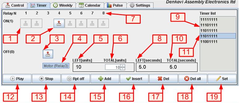
1) Relay button (disabled). This button is disabled because this relay works in another mode.
2) Timer relay button 'ON'. When some timer relay button is in this position the given relay state is ON. If this button is clicked once the state will become OFF.
3) Timer relay button 'OFF'. When some timer relay button is in this position the given relay state is OFF. If this button is clicked once the state will become ON.
4) Tooltip text. It is displayed when you hold the cursor over some graphical component to see more detailed information for it.
5) LEFT [units]. It shows how many units left from the current running state.
6) TOTAL [units]. It shows how many total units the current running state will be delayed. Note that the user edit only the total units.
7) Relay N (Relay number). The relay number.
8) LEFT [seconds]. It shows how many seconds left from the current running state.
9) Timer list. It represent playlist with all relay states and their delays. The DRM software go through its states sequentialy until the playlist end is reached or go back to the beginning (if repeat is on).
10) TOTAL [seconds]. It shows how many total seconds the current running state will be delayed.
11) Selected state. This is the current state. When some state is selected from the timer list, its state is displayed by the timer relay buttons and its delay is shown in TOTAL [units].
12) Timer button 'Play/Pause'. This button starts/pause playing the timer playlist. Note that there must be at least one state in the timer list to be played.
13) Timer button 'Stop'. This button stops playing the timer playlist.
14) Timer button 'Rpt on/off'. This button enable/disable repeating the timer playlist.
15) Timer button 'Add'. This button adds new state in the timer playlist.
16) Timer button 'Insert'. This button inserts new state in the timer playlist. The new state is inserted after the selected state.
17) Timer button 'Del'. This button deletes the currently selected state from the timer playlist.
18) Timer button 'Del all'. This button deletes all the states from the timer playlist.
19) Timer button 'Set'. This button changes the currenty selected state from the timer playlist.
Weekly mode
This mode is for making weekly schedule. The user may set each day form the week ON and OFF turning time for each relay.
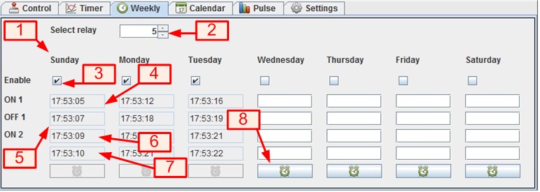
1) Day of week.
2) Selected relay. This is the curently selected relay for weekly mode. All the settings that are made from weekly mode tab are for this relay.
3) Enable/disable. Enables/disables relay setting for this day of week. When it is checked, ON and OFF time fields can not be changed.
4) ON time 1. This is the time on this day of week when the rely must be turned ON.
5) OFF time 1. This is the time on this day of week when the rely must be turned OFF.
6) ON time 2. This is the time on this day of week when the rely must be turned ON.
7) OFF time 2. This is the time on this day of week when the rely must be turned OFF.
8) Button 'Now'. Fills up the ON and OFF time fileds with the current time.
Note that if DRM software is started and the current time is between 00:00:00 and the lesser time, the relay will not be set automaticaly in OFF. If you don't want to set it in OFF state, you must set option for get relays states on connect. In this way the state eventually won't be changed.
This mode is combination from the timer mode and weekly mode. There is playlist (also called calendar list or calendar eventlist) with dates (days) and states.
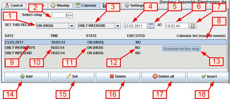
1) Relay state combo box. This combo box contains two possible relay states - ON and OFF.
2) Selected relay. This is the curently selected relay for calendar mode. All the settings that are made from calendar mode tab are for this relay.
3) Day combo box. This combo box contains the following choices:
3.1) AT SPECIFIC DATE - means that the day will be determined by the date field (4).
3.2) ONLY WORK DAYS - means that this will be executed each working day (Monday...Friday) at the given time.
3.3) ONLY WEEKEND - means that this will be executed each weekend day (Saturday and Sunday) at the given time.
3.4) EVERYDAY- means that this will be executed during the whole week, each day at the given time.
4) Date field. The user may fill this field when it is necessary to set the relay at particular date.
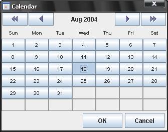
5) Calendar button. This button shows small calendar window for detailed data selection.
6) Time field. The user fills this time field always to add new event in the calendar list.
7) Now button. When it is pressed the time field (6) is filled with the current time.
7) Relay N (Relay number). The relay number.
8) Calendar list. Also called calendar eventlist or calendar playlist. Contains up to 16 events(tasks) for each relay.
9) Event date. This is the date (or days) when the task must be executed.
10) Event time. This is the time when the task must be executed.
11) Event relay state. This is the state in that must be set the current relay on the given date (days) at the given time.
12) Event status. This is the status of the event (task). It may be 'YES' - executed, 'NO' - not executed.
13) Tooltip text. It is displayed when you hold the cursor over some graphical component to see more detailed information for it.
14) Calendar button 'Add'. This button adds new state in the calendar eventlist.
15) Calendar button 'Set'. This button changes the currently selected event from the calendar eventlist
16) Calendar button 'Delete'. This button deletes the currently selected event from the calendar eventlist.
17) Calendar button 'Delete all'. This button deletes all the events from the calendar eventlist.
18) Calendar button 'Insert'. This button inserts new state in the calendar eventlist. The new event is inserted after the selected event.
Pulse mode is cyclic setting the relay ON and OFF. The user may set ON period and OFF period.
.jpg)
1) Disabled. This relay works in another mode.
2) Disabled. This relay works in another mode.
3) Enable/disable puls. Enable/disable pulses for this relay.
4) OFF period. This is how many units the relay will be turned OFF. If you want to see how many seconds is this you just need to position the mouse cursor over this field and a tooltip text will be shown with seconds - (2).
5) Number pulses. This is how many times will be repeated the pulses. If it is 0, this means infinity loop.
6) ON period. This is how many units the relay will be turned ON. If you want to see how many seconds is this you just need to position the mouse cursor over this field and a tooltip text will be shown with seconds - (1).
In this section the user may set the relay name and relay working mode.
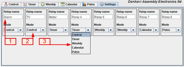
1) Relay name field. The user may edit the relay name from this field.
2) Mode combo box. The selected mode for this relay
3) Available relay modes.
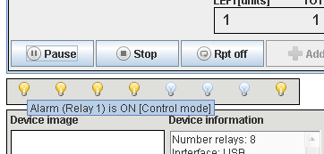
The status of each relay is displayed on the Indicator panel. For more information for this relay the user can get anytime by holding the mouse cursor over the relay bulb and see the tooltip text. For example on the figure below is shown tooltip text for Relay 1 - Alarm (Relay 1) is ON [Control mode]. 'Alarm' is the name for Relay 1, '(Relay 1)' is the relay number, 'ON' is the status of Relay 1 (means that the relay is ON) and '[Control mode]' is the currently selected mode for Relay 1.
Problem: I am getting the following mesage:
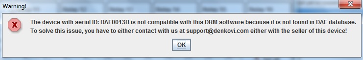
Solution: You can contact with us at support@denkovi.com with the MAC addres of your IP module (if ethernet relay board) or the FTDI serial number (if USB relay board) and the ordering information (invoice or ebay purchase number). Then we will activate your software copy. This is most probably your order is done before June 2013 (when DRM 2.0 update is released).
|
|


