Cart is empty.
.png)


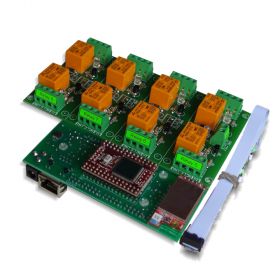
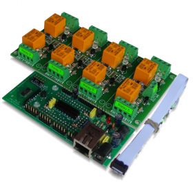
Web SNMP controlled 8 Relay Board v1


Set of IP SNMP controller and Eight channel Relay board. The system may be controlled by WEB browser, windows application, Android software and SNMP commands.
- Brand: Denkovi Assembly Electronics ltd.
- Weight: 0.350 Kgs
Code: DAEnetIP1 + DAE-RB/Ro8-JQC-12V
DAEnetIP1 user manual
Download it from here
General description
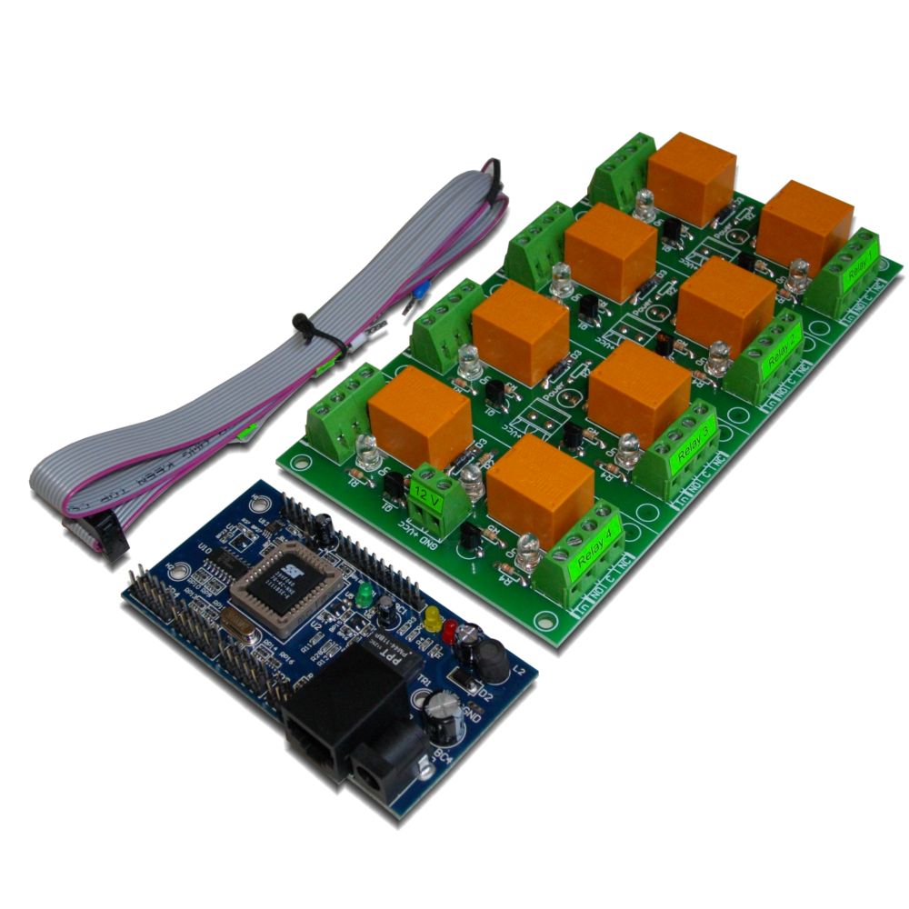
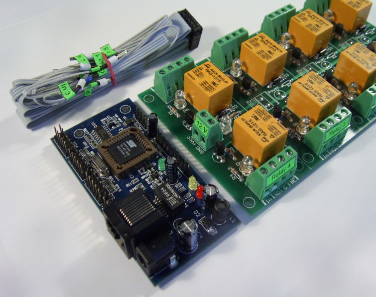
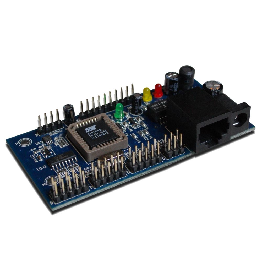
This is set of DAEnetIP1 and Relay card with 8 relays. The relays may be JQC-3FC/T73 or RAS-12-15 (depending on your choice). It is autonomic ethernet device. Just connect the board into your local network or internet and control it from remote PC. You may use special software (DAEnetIP1 manager - available for download at this page) or web browser to switch ON/OFF each relay. The relay card is connected to JP1 of DAEnetIP1. You are free to use the rest of DAEnetIP1 ports for your needs. For full description see the DAEnetIP1 maunal. For suitable power adaptor please look at our store or contact with us (if you have questions for the power supply source).
Features
- SNMP v1 protocol
- SNMPTRAP, SNMPGET, SNMPSET
- Integrated web server - access via web browser
- 8 SPDT relays RAS-12-15 or JQC-3FC/T73
- 12V DC power supply
- Integrated overvoltage protection
- Supported by DRM Software (Windows/Linux)
- Configuration utility - DAEnetIP1 Manager
- Command line utility
Application examples
- Security and fire alarm systems
- Manual or automatic device restart if event occur
- Management/monitoring for industrial
- Sensor information processing
- Remote electrical devices control
- Remote Lock/unlock doors
- Suitable for school and university education
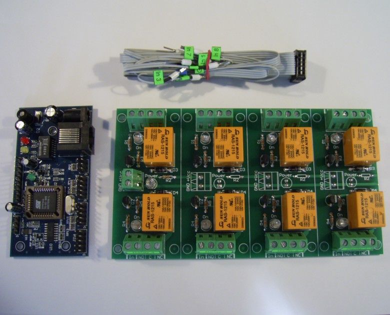
The kit includes
- 1 x DAEnetIP1 Ethernet controller - user manual DAEnetIP1_UM.pdf

- 1 x Eight Channel Relay board
- Flat ribbon labeled cabel
- DAEnetIP1 Manager configuration utility -
 DAEnetIP1Manager.exe
 - DRM Software - Denkovi Relay Manager Software. The software is available for download from this link -setup.exe
Eight channel relay Board
- Power supply - 12VDC, 300mA
- 8 SPDT relays - JQC-3F/T73 or RAS-1215. (Depending on your choice)
- MAX. SWITCHING CURRENT PER SINGLE RELAY CHANNEL:
- Relay JQC-3F/T73
- 7A / 250VAC
- 10A / 125VAC
- 12A / 120VAC
- 10A / 28VDC
- Relay RAS-1215
- 10A / 250VAC
- 15A / 120VAC
- 15A / 24VDC
- Relay JQC-3F/T73
- Contact type: Normal Opened (NO), Normal Closed (NC)
- PCB parameters : FR4 / 1.5mm / two layers / metallized holes / HAL / white stamp / solder mask
- Extra PCB openings for better voltage isolation
- Doubled high current tracks
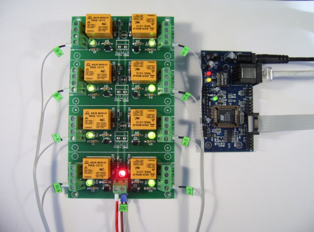
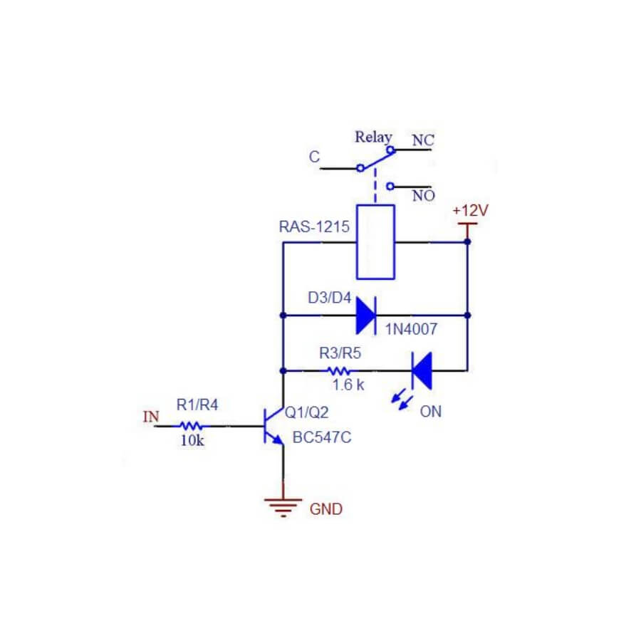
- Input voltage: 3V-15V (1.5mA max) must be given to the "In" to switch the relay ON
- May be controlled directly by microcontroller TTL logic
- Green leds for relay status
- Red led for power
- Dimensions: 85mm / 150mm / 20mm
- Mounting holes diameter: 3mm
Single relay channel schematic
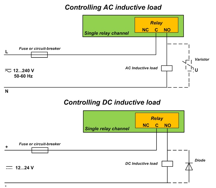
How to connect inductive loads to the relay board
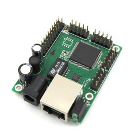
DAEnetIP1 description
DAEnetIP1 is powerful and easy for use at the same time ethernet controller for remote monitoring and control via internet. No programing skills needed. Just connect DAEnetIP1 to your LAN or wireless router for example and you may control different elcetrical devices, scan sensors, make pulses with adjustable width and so on. If you connect for example in suitable way thermo sensor to one of the eight analog inputs and relay to one of the eight digital outputs you have standalone thermoregolator without even need of LAN connection. The auction contains some additional instructions how to access input/output lines of DAEnetIP1(via WEB browser IE/Mozilla, DAEnetIP1 manager or SNMP commands via command promt).
DAEnetIP1 Parameters
- 10/100 Full duplex Ethernet interface
- SNMP v1 TRAP
- SNMP v1 (snmpget,snmpset)
- WEB interface with authorization
- 8 Digital inputs/outpus
- 8 Digital outputs
- 4 Digital outputs for relays
- 8 Analog inputs (each is with 10 bit resoution)
- Onboard temperature sensor
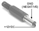
- Power supply: 12 VDC (the middle pin is +12VDC)
- Consumtion: 117mA/12V DC
- Integrated overvoltage protection
- Working temperature from 0 to +70 Celsius
- Storage temperature from -40 to +125 Celsius
- Humidity from 10% to 80% non-condensing
DAEnetIP1 connection to the Ethernet network is done with UTP Cat.5 cable with RJ45 connector. Auto MDIX. 8 seconds after power on, the device is ready for work. For more information - here
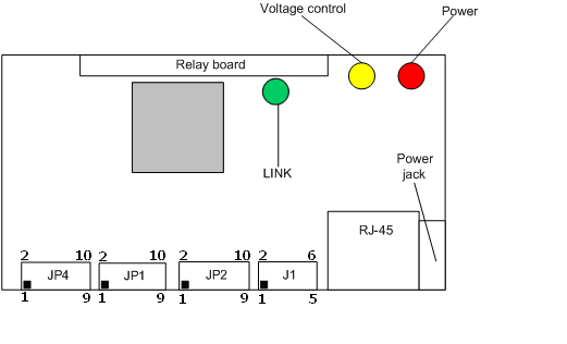
Schematic description
- JP4 – 8 x ADC inputs
- JP1 – 8 x digital outputs (GPO)
- JP2 – 8 x digital I/O (GPIO)
- J1 – Unused
- RJ-45 – UTP cable connector
- Power jack – power connector
- Relay board terminal – 4 digital outputs for relays
LEDs:
- “power” – power 12V DC ready
- “link” – Ethernet activity LED.
- “voltage control” – power 3.3V DC ready
Power supply requirements
The power supply is very important! There are some requirements that must be kept for proper work of the DAEnetIP1 controller. We recommend power supply that fit the following reqiurements:
- Power supply: DC 12 V 1000 mA (stabilized and filtered)
- Polarity: Center positive, the inner pin of the power supply adaptor jack must be +12VDC.

- Before using the power supply, measure the output voltage with voltmeter. The output voltage must be 12V DC +/- 5%

The controller power DC jack is shown on the figure belollow. The polarity is center positive tip, the midle pin is +12VDC:
DAEnetIP1 does not have reverese polarity protection. Supply with different polarity shown in this auction will damage the controller !
If you are not sure what power supply to use, you have doubts, you need power supply or you have whatever questions about the power supply for this device, please feel free to contact us !!! If you need power supply adaptor, please look at our store. We sell suitable adaptor for this device.
Default (Factory) Settings
DAEnetIP1 connection to the Ethernet network is done with UTP Cat.5 cable with RJ45 connector. Auto MDIX. 8 seconds after power on, the device is ready for work.
IP - 192.168.0.100
Netmask - 255.255.255.0
DG - 192.168.0.1
DHCP – Disabled
WEB username - admin
WEB password - admin
SNMP RW community - private
SNMP RO community - none
How to reset to default(Factory) settings:
Software restart:
- From nav-menu -> „Restart"
- Restart – restart the device
- Reset DAEnetIP1 – Restart the device and reset to default values
Hardware restart:
- power off the device
- place jumper on J1 pin 4 and 6
- power on the device and wait around 10 seconds
- power off the device
- remove the jumper
- power on the device
Important: If you lose access to the controller somehow (forget IP or whatever) DO NOT UPDATE THE FIRMWARE, BUT SIMPLY MAKE HARDWARE RESET ! If this does not help, please contact with us and we will try to help you!
Connecting to PC
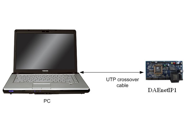
- Connect your DAEnetIP1 controller (or kit) with UTP cable.
- Connect the PC with the other end of this cable
- Check out carefully that there is not danger of short cuts or metal surface around the controller.
- If there are additional wires from the DAEnetIP1 controller connect them (to the relay board or any other device)
- Check out the power supply you will use for DAEnetIP1 if it is correct according this auction (it is 12VDC and center positive tip)
- Plug the DC jack from the power adaptor to the device DC plug.
- TURN ON the power supply source.
- The power led (red one) must be on
- Adjust your PC IP to be 192.168.0.1
- Access the device via Web browser - type its IP (192.168.0.100) in the address bar and use admin / admin for username / password.
Caution: Do not touch the device with hands during power on !
Connecting to router
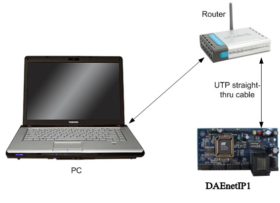
- We assume you have PC IP - 192.168.1.2, Router IP - 192.168.1.1 and DAEnetIP1 factory IP - 192.168.0.100
- Connect your DAEnetIP1 controller (or kit) with UTP cable.
- Connect the PC with the other end of this cable.
- Plug the DC jack from the power adaptor to the device DC plug.
- TURN ON the power supply source.
- The power led (red one) must be on
- Adjust your PC IP to be 192.168.0.1
- Access the device via Web browser - type its IP (192.168.0.100) in the address bar and use admin / admin for username / password.
- Change the DAEnetIP1 IP to be 192.168.1.3 (to mach your network)
- Change back the old IP of your PC - 192.168.1.2
- Turn off the DAEnetIP1 controller
- Unplug the UTP cable from PC and conect it to router.
- Power on the DAEnetIP1 controller
- Type in browser 192.168.1.3 ( the new IP) and access the controller.
Caution: Do not touch the device with hands during power on !
DAEnetIP1 I/O ports description - GPO (JP1)
| Pin No. | bit | Func | direction | pull-up | buffer |
| 1 | 0 | GPO | OUT | 3v3/4k7 | 100 ohm |
| 2 | 1 | GPO | OUT | 3v3/4k7 | 100 ohm |
| 3 | 2 | GPO | OUT | 3v3/4k7 | 100 ohm |
| 4 | 3 | GPO | OUT | 3v3/4k7 | 100 ohm |
| 5 | 4 | GPO | OUT | 3v3/4k7 | 100 ohm |
| 6 | 5 | GPO | OUT | 3v3/4k7 | 100 ohm |
| 7 | 6 | GPO | OUT | 3v3/4k7 | 100 ohm |
| 8 | 7 | GPO | OUT | 3v3/4k7 | 100 ohm |
| 9 | - | GND | - | - | - |
| 10 | - | 3v3 | - | - | - |
DAEnetIP1 I/O ports description - GPO (JP2)
| Pin No. | bit | Func | direction | pull-up | buffer |
| 1 | 0 | GPIO | IN/OUT | 3v3/4k7 | 100 ohm |
| 2 | 1 | GPIO | IN/OUT | 3v3/4k7 | 100 ohm |
| 3 | 2 | GPIO | IN/OUT | 3v3/4k7 | 100 ohm |
| 4 | 3 | GPIO | IN/OUT | 3v3/4k7 | 100 ohm |
| 5 | 4 | GPIO | IN/OUT | 3v3/4k7 | 100 ohm |
| 6 | 5 | GPIO | IN/OUT | 3v3/4k7 | 100 ohm |
| 7 | 6 | GPIO | IN/OUT | 3v3/4k7 | 100 ohm |
| 8 | 7 | GPIO | IN/OUT | 3v3/4k7 | 100 ohm |
| 9 | - | GND | - | - | - |
| 10 | - | 3v3 | - | - | - |
DAEnetIP1 I/O ports description - Relay Outputs (JP3)
| Pin No. | bit | Func | direction | pull-up | buffer |
| 1 | 0 | GPO | OUT | 3v3/2k2 | - |
| 2 | 1 | GPO | OUT | 3v3/2k2 | - |
| 3 | 2 | GPO | OUT | 3v3/2k2 | - |
| 4 | 3 | GPO | OUT | 3v3/2k2 | - |
| 5 | - | PWR_EN | OUT | - | - |
| 6 | - | Vin | OUT | - | - |
| 7 | - | Vin | OUT | - | - |
| 8 | - | GND | - | - | - |
| 9 | - | GND | - | - | - |
| 10 | - | GND | - | - | - |
DAEnetIP1 I/O ports description - ADC (JP4)
| Pin No. | bit | Func | direction | pull-up | buffer |
| 1 | 0 | Channel 0 | Ain | - | - |
| 2 | 1 | Channel 1 | Ain | - | - |
| 3 | 2 | Channel 2 | Ain | - | - |
| 4 | 3 | Channel 3 | Ain | - | - |
| 5 | 4 | Channel 4 | Ain | - | - |
| 6 | 5 | Channel 5 | Ain | - | - |
| 7 | 6 | Channel 6 | Ain | - | - |
| 8 | 7 | Channel 7 | Ain | - | - |
| 9 | - | GND | - | - | - |
| 10 | - | V ref | - | - | - |
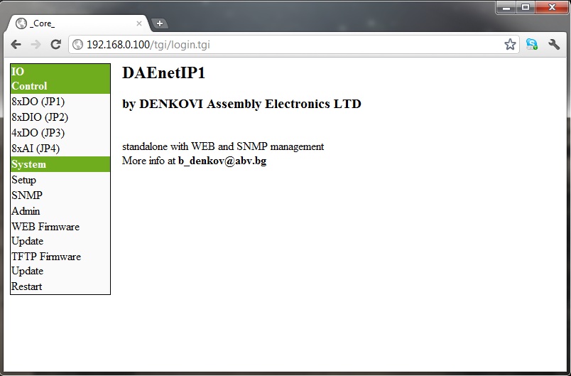
Access DAEnetIP1 via Web Browser
Android Application
You may use this inexpensive but very useful application for your Android smart phone. You may controll DAEnetIP1 digital outputs or read the DAEnetIP1 analog inputs. With the Gauge functions you may set the measured range and value (C, F, Voltage...). Output timers can be set also. The application is marketed by iSwitch, LLC.
Download it from the Android Market


DAEnetIP1 device controlled by Android Software by iSwitch, LLC over internet
![]()
The App documentation may be downloaded from here
![]()
For more information about the Android App you may contact with us or use the developer site link
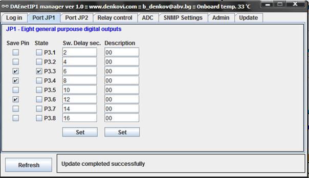
Access JP1 via DAEnetIP1 manager
JP1 is 8 bit digital output port. It can be controlled via web browser, DAEnetIP1 manager, snmp commands or via its corresponding ADC input. This is the port that controls the 8 relay channels !
SNMP Commands
snmpget -v1 -c private 192.168.0.100 DenkoviMIB::p6lock.1 - Get JP1 Pin 1 lock value
snmpget -v1 -c private 192.168.0.100 DenkoviMIB::p6lock.8 - Get JP1 Pin 8 lock value
snmpget -v1 -c private 192.168.0.100 DenkoviMIB::p6state.1 - Get JP1 Pin 1 state value
snmpget -v1 -c private 192.168.0.100 DenkoviMIB::p6state.8 - Get JP1 Pin 8 state value
snmpget -v1 -c private 192.168.0.100 DenkoviMIB::p6delay.1 - Get JP1 Pin 1 delay value
snmpget -v1 -c private 192.168.0.100 DenkoviMIB::p6delay.8 - Get JP1 Pin 8 delay value
snmpget -v1 -c private 192.168.0.100 DenkoviMIB::p6description.1 - Get JP1 Pin 1 description value
snmpget -v1 -c private 192.168.0.100 DenkoviMIB::p6description.8 - Get JP1 Pin 8 description value
snmpset -v1 -c private 192.168.0.100 DenkoviMIB::p6lock.1 i 0 - Set JP1 Pin 1 lock value
snmpset -v1 -c private 192.168.0.100 DenkoviMIB::p6lock.8 i 1 - Set JP1 Pin 8 lock value
snmpset -v1 -c private 192.168.0.100 DenkoviMIB::p6state.1 i 0 - Set JP1 Pin 1 state value
snmpset -v1 -c private 192.168.0.100 DenkoviMIB::p6state.8 i 1 - Set JP1 Pin 8 state value
snmpset -v1 -c private 192.168.0.100 DenkoviMIB::p6delay.1 i 10 - Set JP1 Pin 1 delay value
snmpset -v1 -c private 192.168.0.100 DenkoviMIB::p6delay.8 i 121 - Set JP1 Pin 8 delay value
snmpset -v1 -c private 192.168.0.100 DenkoviMIB::p6description.1 s "DO_1" - Set JP1 Pin 1 description value
snmpset -v1 -c private 192.168.0.100 DenkoviMIB::p6description.8 s "DO_8" - Set JP1 Pin 8 description value
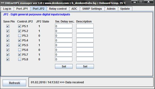
Access JP2 via DAEnetIP1 manager
JP2 is 8 bit digital bidirectional user configurable input/output port. When it is ouput can be controlled via web browser, DAEnetIP1 manager, snmp commands. When it is input may be monitored via DAEnetIP1 manager and snmp commands. When there is JP2 pin level change DAEnetIP1 sends trap message to the given trap servers.
SNMP Commands
snmpget -v1 -c private 192.168.0.100 DenkoviMIB::JP2Lock.1 - Get JP2 Pin 1 lock value
snmpget -v1 -c private 192.168.0.100 DenkoviMIB::JP2Lock.8 - Get JP2 Pin 8 lock value
snmpget -v1 -c private 192.168.0.100 DenkoviMIB::JP2State.1 - Get JP2 Pin 1 state value
snmpget -v1 -c private 192.168.0.100 DenkoviMIB::JP2State.8 - Get JP2 Pin 8 state value
snmpget -v1 -c private 192.168.0.100 DenkoviMIB::JP2Delay.1 - Get JP2 Pin 1 delay value
snmpget -v1 -c private 192.168.0.100 DenkoviMIB::JP2Delay.8 - Get JP2 Pin 8 delay value
snmpget -v1 -c private 192.168.0.100 DenkoviMIB::JP2Description.1 - Get JP2 Pin 1 description value
snmpget -v1 -c private 192.168.0.100 DenkoviMIB::JP2Description.8 - Get JP2 Pin 8 description value
snmpget -v1 -c private 192.168.0.100 DenkoviMIB::JP2Value.1 - Get JP2 Pin 1 value
snmpget -v1 -c private 192.168.0.100 DenkoviMIB::JP2Value.8 - Get JP2 Pin 8 value
snmpset -v1 -c private 192.168.0.100 DenkoviMIB::JP2Lock.1 i 0 - Set JP2 Pin 1 lock value
snmpset -v1 -c private 192.168.0.100 DenkoviMIB::JP2Lock.8 i 1 - Set JP2 Pin 8 lock value
snmpset -v1 -c private 192.168.0.100 DenkoviMIB::JP2State.1 i 0 - Set JP2 Pin 1 state value
snmpset -v1 -c private 192.168.0.100 DenkoviMIB::JP2State.8 i 1 - Set JP2 Pin 8 state value
snmpset -v1 -c private 192.168.0.100 DenkoviMIB::JP2Delay.1 i 10 - Set JP2 Pin 1 delay value
snmpset -v1 -c private 192.168.0.100 DenkoviMIB::JP2Delay.8 i 121 - Set JP2 Pin 8 delay value
snmpset -v1 -c private 192.168.0.100 DenkoviMIB::JP2Description.1 s "DIO_1" - Set JP2 Pin 1 description value
snmpset -v1 -c private 192.168.0.100 DenkoviMIB::JP2Description.8 s "DIO_8" - Set JP2 Pin 8 description value
Note:
JP2 can be used either digital outputs either digital inputs. The inputs visualization is implemented only over SNMP and DAEnetIP1 manager (it is not implemented via web yet). To use a JP2 pin as input its state must be set (“1”). To do this set the checkbox under label “Control JP2”.
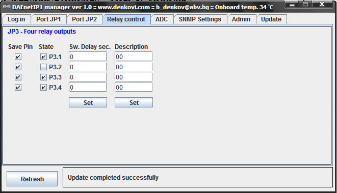
Access JP3 via DAEnetIP1 manager
JP3 is 4 bit digital output port for switching relays. It can be controlled via web browser, DAEnetIP1 manager, snmp commands or via its corresponding ADC input.The management rules are same as JP1 digital I/O management. It is used only R0,R1,R2 and R3.
SNMP Commands
snmpget -v1 -c private 192.168.0.100 DenkoviMIB::RelayLock.1 - Get JP2 Pin 1 lock value
snmpget -v1 -c private 192.168.0.100 DenkoviMIB::RelayLock.4 - Get JP2 Pin 4 lock value
snmpget -v1 -c private 192.168.0.100 DenkoviMIB::RelayState.1 - Get JP2 Pin 1 state value
snmpget -v1 -c private 192.168.0.100 DenkoviMIB::RelayState.4 - Get JP2 Pin 4 state value
snmpget -v1 -c private 192.168.0.100 DenkoviMIB::RelayDelay.1 - Get JP2 Pin 1 delay value
snmpget -v1 -c private 192.168.0.100 DenkoviMIB::RelayDelay.4 - Get JP2 Pin 4 delay value
snmpget -v1 -c private 192.168.0.100 DenkoviMIB::RelayDescription.1 - Get JP2 Pin 1 description value
snmpget -v1 -c private 192.168.0.100 DenkoviMIB::RelayDescription.4 - Get JP2 Pin 4 description value
snmpset -v1 -c private 192.168.0.100 DenkoviMIB::RelayLock.1 i 0 - Set JP2 Pin 1 lock value
snmpset -v1 -c private 192.168.0.100 DenkoviMIB::RelayLock.4 i 1 - Set JP2 Pin 4 lock value
snmpset -v1 -c private 192.168.0.100 DenkoviMIB::RelayState.1 i 0 - Set JP2 Pin 1 state value
snmpset -v1 -c private 192.168.0.100 DenkoviMIB::RelayState.4 i 1 - Set JP2 Pin 4 state value
snmpset -v1 -c private 192.168.0.100 DenkoviMIB::RelayDelay.1 i 10 - Set JP2 Pin 1 delay value
snmpset -v1 -c private 192.168.0.100 DenkoviMIB::RelayDelay.4 i 121 - Set JP2 Pin 4 delay value
snmpset -v1 -c private 192.168.0.100 DenkoviMIB::RelayDescription.1 s "DIO_1" - Set JP2 Pin 1 description value
snmpset -v1 -c private 192.168.0.100 DenkoviMIB::RelayDescription.4 s "DIO_4" - Set JP2 Pin 4 description value
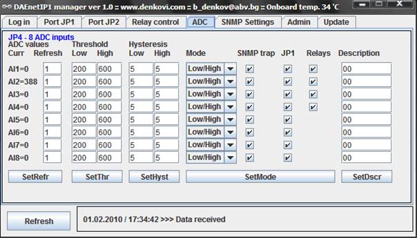
Access JP4 via DAEnetIp1 manager
JP4 is 8 channel x 10-bit ADC input port (0 - 2.5 VDC) with 2.5VDC refferent voltage. It can be monitored via web browser, DAEnetIP1 manager, snmp commands. When some ADC input crosses given high/low threshold may be done the following: 1) a trap message may be sent. 2) JP1 pin state may be changed. 3) JP3 pin state may be changed.
SNMP Commands
snmpget -v1 -c private 192.168.0.100 DenkoviMIB::Value.1 - Get JP4 Pin 1 value
snmpget -v1 -c private 192.168.0.100 DenkoviMIB::Value.8 - Get JP4 Pin 8 value
snmpget -v1 -c private 192.168.0.100 DenkoviMIB::SNMPRefresh.1 - Get JP4 Pin 1 SNMP refresh interval value
snmpget -v1 -c private 192.168.0.100 DenkoviMIB::SNMPRefresh.8 - Get JP4 Pin 8 SNMP refresh interval value
snmpget -v1 -c private 192.168.0.100 DenkoviMIB::LowThreshold.1 - Get JP4 Pin 1 LT value
snmpget -v1 -c private 192.168.0.100 DenkoviMIB::LowThreshold.8 - Get JP4 Pin 8 LT value
snmpget -v1 -c private 192.168.0.100 DenkoviMIB::HighThreshold.1 - Get JP4 Pin 1 HT value
snmpget -v1 -c private 192.168.0.100 DenkoviMIB::HighThreshold.8 - Get JP4 Pin 8 HT value
snmpget -v1 -c private 192.168.0.100 DenkoviMIB::LowHysteresis.1 - Get JP4 Pin 1 LH value
snmpget -v1 -c private 192.168.0.100 DenkoviMIB::LowHysteresis.8 - Get JP4 Pin 8 LH value
snmpget -v1 -c private 192.168.0.100 DenkoviMIB::HighHysteresis.1 - Get JP4 Pin 1 HH value
snmpget -v1 -c private 192.168.0.100 DenkoviMIB::HighHysteresis.8 - Get JP4 Pin 8 HH value
snmpget -v1 -c private 192.168.0.100 DenkoviMIB::ChannelDescription.1 - Get JP4 Pin 1 Description value
snmpget -v1 -c private 192.168.0.100 DenkoviMIB::ChannelDescription.8 - Get JP4 Pin 8 Description value
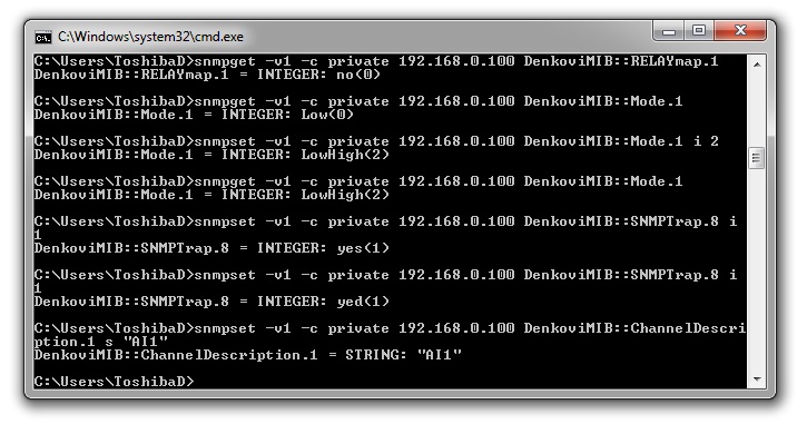
snmpget -v1 -c private 192.168.0.100 DenkoviMIB::Mode.1 - Get JP4 Pin 1 Mode value
snmpget -v1 -c private 192.168.0.100 DenkoviMIB::Mode.8 - Get JP4 Pin 8 Mode value
snmpget -v1 -c private 192.168.0.100 DenkoviMIB::SNMPTrap.1 - Get JP4 Pin 1 SNMPTrap value
snmpget -v1 -c private 192.168.0.100 DenkoviMIB::SNMPTrap.8 - Get JP4 Pin 8 SNMPTrap value
snmpget -v1 -c private 192.168.0.100 DenkoviMIB::GPIOmap.1 - Get JP4 Pin 1 GPIOmap value
snmpget -v1 -c private 192.168.0.100 DenkoviMIB::GPIOmap.8- Get JP4 Pin 8 GPIOmap value
snmpget -v1 -c private 192.168.0.100 DenkoviMIB::RELAYmap.1 - Get JP4 Pin 1 RELAYmap value
snmpget -v1 -c private 192.168.0.100 DenkoviMIB::RELAYmap.8 - Get JP4 Pin 8 RELAYmap value
snmpset -v1 -c private 192.168.0.100 DenkoviMIB::SNMPRefresh.1 i 1 - Set JP4 Pin 1 SNMP refresh interval value
snmpset -v1 -c private 192.168.0.100 DenkoviMIB::SNMPRefresh.8 i 80 - Set JP4 Pin 8 SNMP refresh interval value
snmpset -v1 -c private 192.168.0.100 DenkoviMIB::LowThreshold.1 i 200 - Set JP4 Pin 1 LT value
snmpset -v1 -c private 192.168.0.100 DenkoviMIB::LowThreshold.8 i 0 - Set JP4 Pin 8 LT value
snmpset -v1 -c private 192.168.0.100 DenkoviMIB::HighThreshold.1 i 600 - Set JP4 Pin 1 HT value
snmpset -v1 -c private 192.168.0.100 DenkoviMIB::HighThreshold.8 i 0 - Set JP4 Pin 8 HT value
snmpset -v1 -c private 192.168.0.100 DenkoviMIB::LowHysteresis.1 - Set JP4 Pin 1 LH value
snmpset -v1 -c private 192.168.0.100 DenkoviMIB::LowHysteresis.8 - Set JP4 Pin 8 LH value
snmpset -v1 -c private 192.168.0.100 DenkoviMIB::HighHysteresis.1 - Set JP4 Pin 1 HH value
snmpset -v1 -c private 192.168.0.100 DenkoviMIB::HighHysteresis.5 - Set JP4 Pin 8 HH value
snmpset -v1 -c private 192.168.0.100 DenkoviMIB::ChannelDescription.1 s "AI1" - Set JP4 Pin 1 Description value
snmpset -v1 -c private 192.168.0.100 DenkoviMIB::ChannelDescription.8 s "AI8" - Set JP4 Pin 8 Description value
snmpset -v1 -c private 192.168.0.100 DenkoviMIB::Mode.1 i 0 - Set JP4 Pin 1 Mode value
snmpset -v1 -c private 192.168.0.100 DenkoviMIB::Mode.8 i 2 - Set JP4 Pin 8 Mode value
snmpset -v1 -c private 192.168.0.100 DenkoviMIB::SNMPTrap.1 i 0 - Set JP4 Pin 1 SNMPTrap value
snmpset -v1 -c private 192.168.0.100 DenkoviMIB::SNMPTrap.8 i 1 - Set JP4 Pin 8 SNMPTrap value
snmpset -v1 -c private 192.168.0.100 DenkoviMIB::GPIOmap.1 i 0 - Set JP4 Pin 1 GPIOmap value
snmpset -v1 -c private 192.168.0.100 DenkoviMIB::GPIOmap.8 i 1 - Set JP4 Pin 8 GPIOmap value
snmpset -v1 -c private 192.168.0.100 DenkoviMIB::RELAYmap.1 i 0 - Set JP4 Pin 1 RELAYmap value
snmpset -v1 -c private 192.168.0.100 DenkoviMIB::RELAYmap.8 i 1 - Set JP4 Pin 8 RELAYmap value
Command line (net-snmp)
Steps for Install net-snmp library. In this way you will be able to control the ethernet controller with command line.
- Download the last version net-snmp binary for windows from http://net-snmp.sourceforge.net/download. The file must look like net-snmp-X.X.X.X-X.win32.exe
- Install the downloaded file. Leave the default options. The packet will be install in c:\usr by default.
- Download the DAEnetIP1 MIB file from here
- Copy the mib file here c:\usr\share\snmp\mibs
- Add new line in the file c:\usr\etc\snmp\snmp.conf with the "mibs all" directive.
- Now you can test different commands for OID access, supported by this module. Their names you may see in the DAEnetIP1.mib file.
DRM Software
The device is supported by DRM Software. DRM Software is Windows/Linux software for controlling all our relay boards. Supported OS:
Windows: tested on XP, Vista, 7 and 8
Linux: tested on Ubuntu and OpenSuse
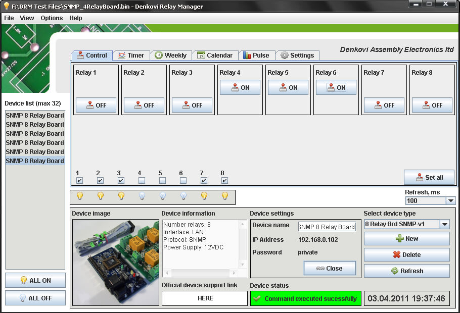
DRM Software image - control mode for Internet / Ethernet Eight Channel Relay Board
![]() For more information about DRM Software, documentation and download - here
For more information about DRM Software, documentation and download - here
![]() Download the last version (install package) - DRMsetup.exe
Download the last version (install package) - DRMsetup.exe
![]() Download the last version (intstall archive) - DRMsetup.rar
Download the last version (intstall archive) - DRMsetup.rar
Demo Video
Useful links
DAEnetIP1
- DAEnetIP1 Ethernet controller user manual (English) - DAEnetIP1_UM.pdf
 DAEnetIP1 Manager configuration Utility (executable) - DAEnetIP1Manager.exe
 DAEnetIP1 Manager configuration utility (archive) - DAEnetIP1Manager.rar
 DAEnetIP1 Tutorials - here
- DAEnetIP1 Burner or the easier way how to update the firmware of DAEnetIP1, DAEnetIP2 and DAEnetIP3 - here (RECOMMEND)
- Free command line tool for executing SNMP commands - here
- Step-by-step guide how to install windows command line application (netsnmp) for executing SNMP commands - How_to_install_netsnmp.pdf
- Java SNMP library - here
DRM Software
- DRM Software (executable) - setup.exe
- DRM Software (archive) - setup.rar
 DRM Software support page - here
- Java (Netbeans) - Example for accessing DAEnetIP1 controller. Works in Linux / Windows / Mac
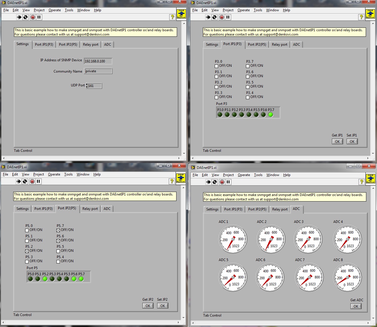
- labVIEW 2011 - basic snmp manager for DAEnetIP1 build with labVIEW. For download please contact us
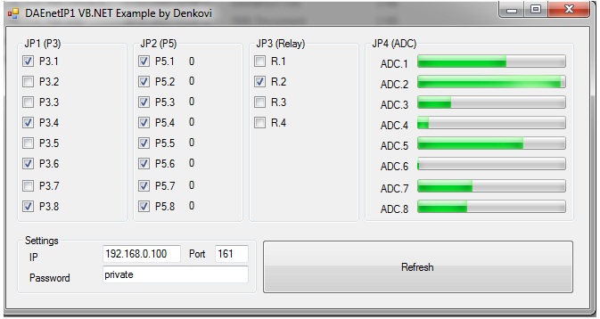
- VB .NET Express 2010 - Very simple demo. It demonstrates how to set and get DAEnetIP1 ports values. For download please contact us
-
DAEnetIP2 - SNMP Ethernet controller with 24 digital/analog I/O
Standalone SNMP and Web based internet/ethernet module (IP controller). It is suitable for home automation, data acquisition, relays controlling, sensors monitoring, fire alarm systems and so on. It has 24 digital/analog I/O. Supported by DRMv3 software. Works with Home Assistant, Domoticz and OpenHAB home automation systems as well as with Node-RED IoT platform. It is possible to be controlled by: configuration software, command line, Android/iOS app, web browser, HTTP API commands
Price: $63.00 -
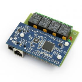
Web SNMP controlled 4 Relay Board
This is relay card based on DAEnetIP1 snmp controller with 4 SPDT channels. Additionaly it has 8 digital outputs, 8 digital inputs/outputs and 8 analog inputs. Connecting the snmp relay board into your local network allows to control electrical devices from another computer or mobile smartphone (tablet) from any location all over the world. You may control it via DAEnetIP1 Manager, command line, browser or Smartphone. For developers we provide software examples in Java, .NET, Labview, PHP. The relay card can be used for home automation, industrials, sensor monitoring or embedding in larger systems.
Price: $69.50Out of stock -
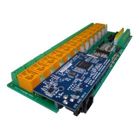
Internet/Ethernet 12 Channel Relay Board - I/O, SNMP, Web
Ethernet SNMP and WEB relay I/O module based on DAEnetIP1 with 12 SPDT relays (up to 15A), 8 ADC inputs (0-10V) and 8 digital inputs (0-12V). Suitable for controling electrical devices and monitor different sensors from the ethernet network. It can be accessed locally (LAN) or remotely (Internet,WAN) via web browser, computer software, android/iOS smartphone. We provide various software examples for easy integration in your code.
Price: $95.00Out of stock -
Wi-Fi Wireless Relay Board 8 Channels - Web, Telnet, HTTP API, E-mails
This is WiFi Wireless 8 channel SPDT relay module (board) for remote management and control with Virtual Serial Port, TCP/IP, Web, HTTP API, Telnet and serial commands access. It has 8 SPDT Relays, 8 digital inputs, 8 analog inputs and one UART port. Inputs can be adjusted to control relays (standalone work). Also inputs of one controller can control outputs of another over the LAN/WAN (box-to-box mode). It can send E-mails on inputs change as well. Suitable for remote control, home automation, data acquisition, sensor processing, alarm systems, PLC applications. Works with Home Assistant, Domoticz and OpenHAB home automation systems as well as with Node-RED IoT platform. Now with FREE Android and iOS App!
Price: $280.00 -
IP Relay Board 8 Channels - Web, TCP/IP, Telnet, HTTP API, E-mails
This is Internet/Ethernet 8 channel SPDT relay module (board) for remote management and control with Virtual Serial Port, TCP/IP, Web, HTTP API, Telnet and serial commands access. It has 8 SPDT Relays, 8 digital inputs, 8 analog inputs and one UART port. Inputs can be adjusted to control relays (standalone work). Also inputs of one controller can control outputs of another over the LAN/WAN (box-to-box mode). It can send E-mails on inputs change as well. Suitable for remote control, home automation, data acquisition, sensor processing, alarm systems, PLC applications. Works with Home Assistant, Domoticz and OpenHAB home automation systems as well as with Node-RED IoT platform. Now with FREE Android and iOS App!
Price: $190.00


