Cart is empty.
.png)
.png)


This tutorial is about how to read DAEnetIP1 analog inputs
For which devices is this tutorial
This tutorial may be useful for all customers that have our devices based on DAEnetIP1 controller.
|
Order number
|
Device name and link
|
| DAEnetIP1 | DAEnetIP1 |
| DAEnetIP1 + DAE-RB/Ro4_v2 | Internet/Ethernet Four Channel Relay Board |
| DAEnetIP1 + DAE-RB/Ro8-12V | Internet/Ethernet Eight Channel Relay Board - ver.1 |
| DAE-PB-RO12/DI8/AI8 + DAEnetIP1 | SNMP and Web based Data Acqusition I/O Module |
DAEnetIP1 has 8 analog inputs. They are located on JP4 port. The reference voltage is 2.5V DC. So it is possible to connect to JP4 only voltage from 0V DC up to 2.5V DC. Each analog input channel is with 10 bit resolution. And measures from 0 to 1024.
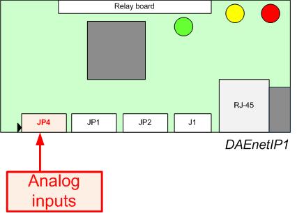
DAEnetIP1 has 8 analog inputs. This is JP4
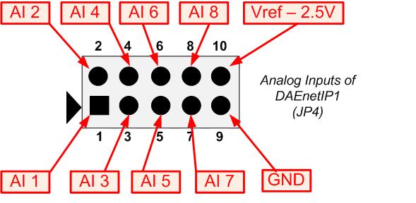
DAEnetIP1 JP4 pinouts
In case you have combination of DAEnetIP1 and our Peripheral board DAE-PB-RO12/DI8/AI8 it is possible to measure voltage from 0V DC to 10V DC. The JP4 of DAEnetIP1 analog inputs port is connected to JP6 of DAE-PB-RO12/DI8/AI8. So the measured voltage must be connected to some input (Ain1...Ain8) of JP6 of DAE-PB-RO12/DI8/AI8
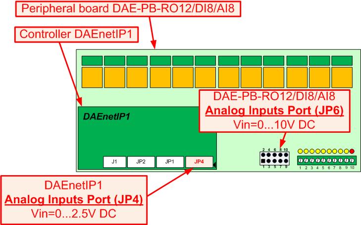
DAEnetIP1 + DAE-PB-RO12/DI8/AI8 combination. The measured voltage must be connected to JP6 port
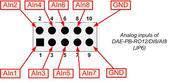
DAE-PB-RO12/DI8/AI8 JP6 Pinout
Bellow are shown steps how to configure and read DAEnetIP1 analog inputs from web browser. In this example we will take analog input 1 (AI1).
- Open your browser and type the address of your DAEnetIP1 device.
- Enter the username and password
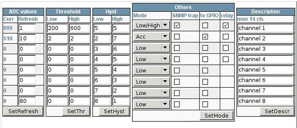
- Go to "ADC"
- Set Low Threshold = 200
- Set High Threshold = 600
- Click "SetThr"
- Set Low Hysteresis = 5
- Set High Hysteresis = 5
- Click "SetHyst"
- Set Mode = Low/High
- Click "SetMode"
- Set Refresh= 1
- Click "SetRefresh"
Now the analog input 1 is configurated and you can read it by clicking refresh button of your browser. The rest analog inputs may be read/configurated the same way.
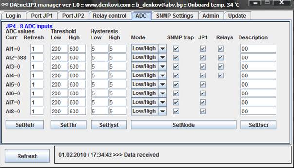
- Open DAEnetIP1 Manager
- Type the IP address of your DAEnetIP1 and passowrd (SNMP RW Community)
- Click "Refresh" to be sure you are connected.
- Go to "ADC"
- Set Low Threshold = 200
- Set High Threshold = 600
- Click "SetThr"
- Set Low Hysteresis = 5
- Set High Hysteresis = 5
- Click "SetHyst"
- Set Mode = Low/High
- Click "SetMode"
- Set Refresh= 1
- Click "SetRefr"
Now when you click refresh you will get the value of ADC channel you want. For example on the mage below it is shown AI2=388.