Cart is empty.
.png)


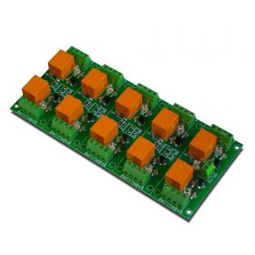
10 Channel relay board for your Arduino or Raspberry PI - 5V


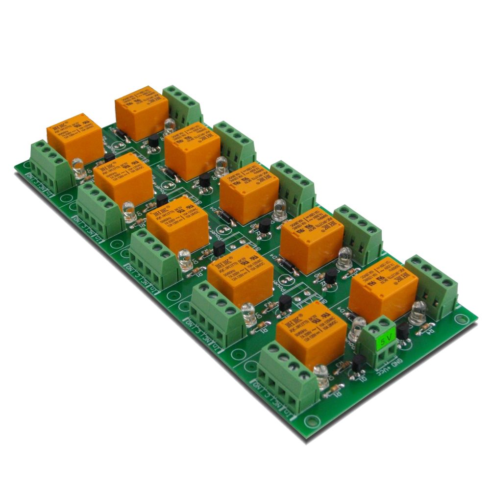
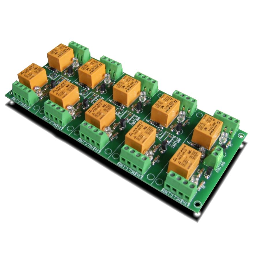
A general purpose 10 SPDT channel relay (power supply 5VDC) board for switching high-current electrical loads (both AC and DC) siuch as motors, lights, pumps, contactors and more. With this relay board, any logic-level signal from 3V up to 30V can be used to activate a relay (it may be controlled direclty by microcontroller TTL logic as well). It can be used successfully for example with PIC,AVR,ARM microcontroller, Raspberry PI, Arduino outputs and other.
- Brand: Denkovi Assembly Electronics ltd.
- Weight: 0.264 Kgs
Code: DAE-RB/Ro10-5V
Product Summary
High-capacity 5V relay board with ten outputs to consolidate many loads on one PCB. This relay module is trusted in labs and cabinets due to Denkovi’s proven design and responsive assistance.
Features
- Power supply - 5VDC;
- Current consumption - 850mA (when all relays are ON);
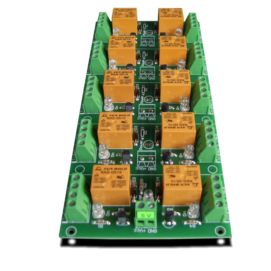
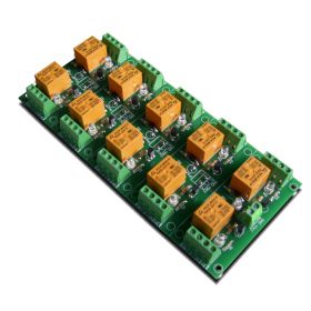
- 10 SPDT relays - JQC-3F/T73 DC5V or RAS-05-15 (depending on your choice during purchase)*;
- Maximum switching current per single relay channel:
- For relay type JQC-3F/T73 DC5V (7A / 250VAC, 10A / 125VAC, 12A / 120VAC, 10A / 28VDC);
- For relay type RAS-05-15 (10A / 250VAC, 15A / 120VAC, 15A / 24VDC);
- Contact type: Normal Opened (NO), Normal Closed (NC);
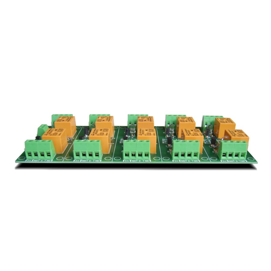
- Screw terminals for inputs and outputs;
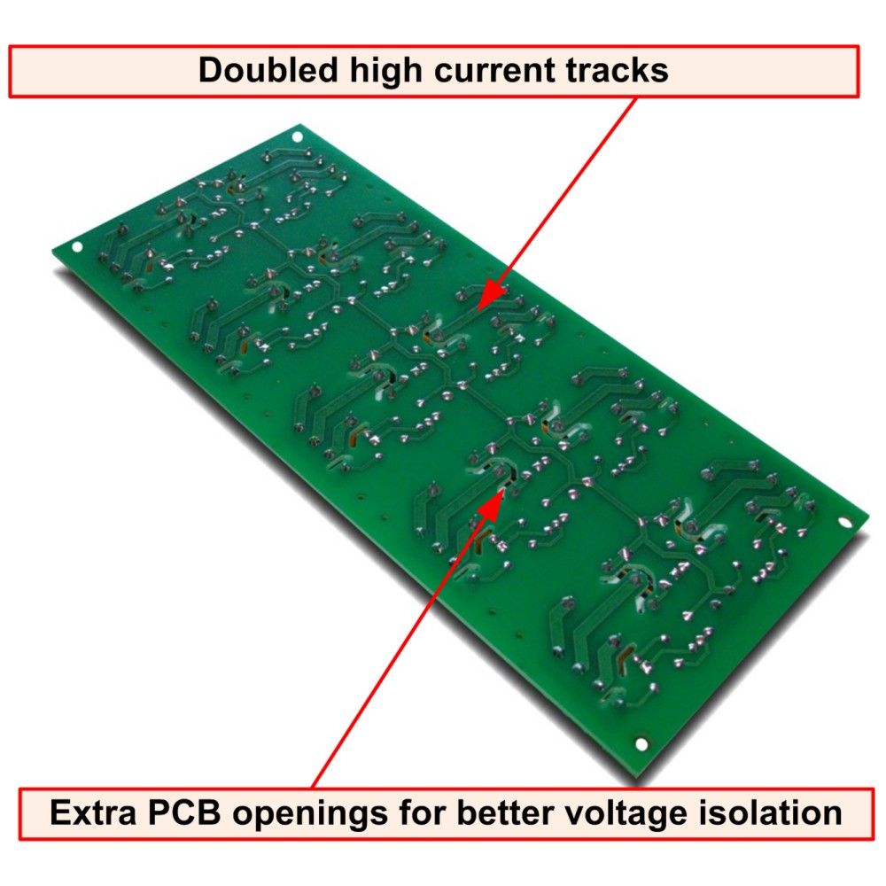
- PCB parameters : FR4 / 1.5mm / two layers / metallized holes / HAL / white stamp / solder mask;
- Extra PCB openings for better voltage isolation;
- Doubled high current tracks;
- Protection diode for each relay;
- Input voltage: 3V - 30V (1.5mA max) must be given to the "In" to switch the relay ON;
- May be controlled directly by TTL;
- Green leds for relay status;
- Red led for power;
- Dimensions: 85mm / 198mm / 20mm;
- Mounting holes diameter: 3mm;
- PCB dimensions - here;
*The difference between two types of relays (RAS and JQC) is that RAS relays can handle bigger amperage (15A max) while JQC can 12A max.
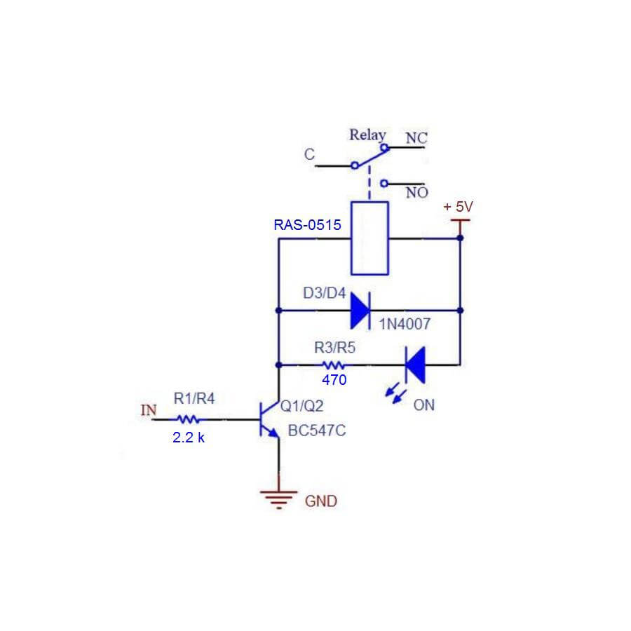
Single relay channel schematic
Add the relay board to your Arduino project
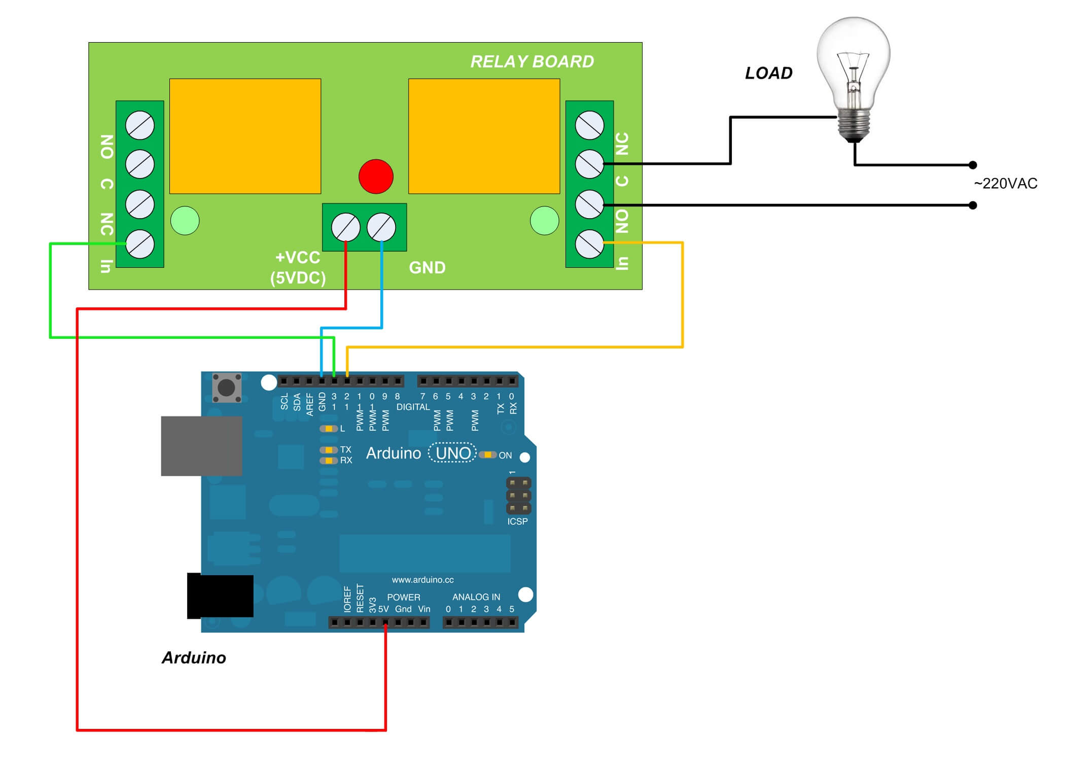
Above is given example for 2 relays only. You can supply either from external power supply source, either from Arduino (however you must consider the maximum allowed current draw from Arduino in this case)
Add the relay board to your Raspberry PI project
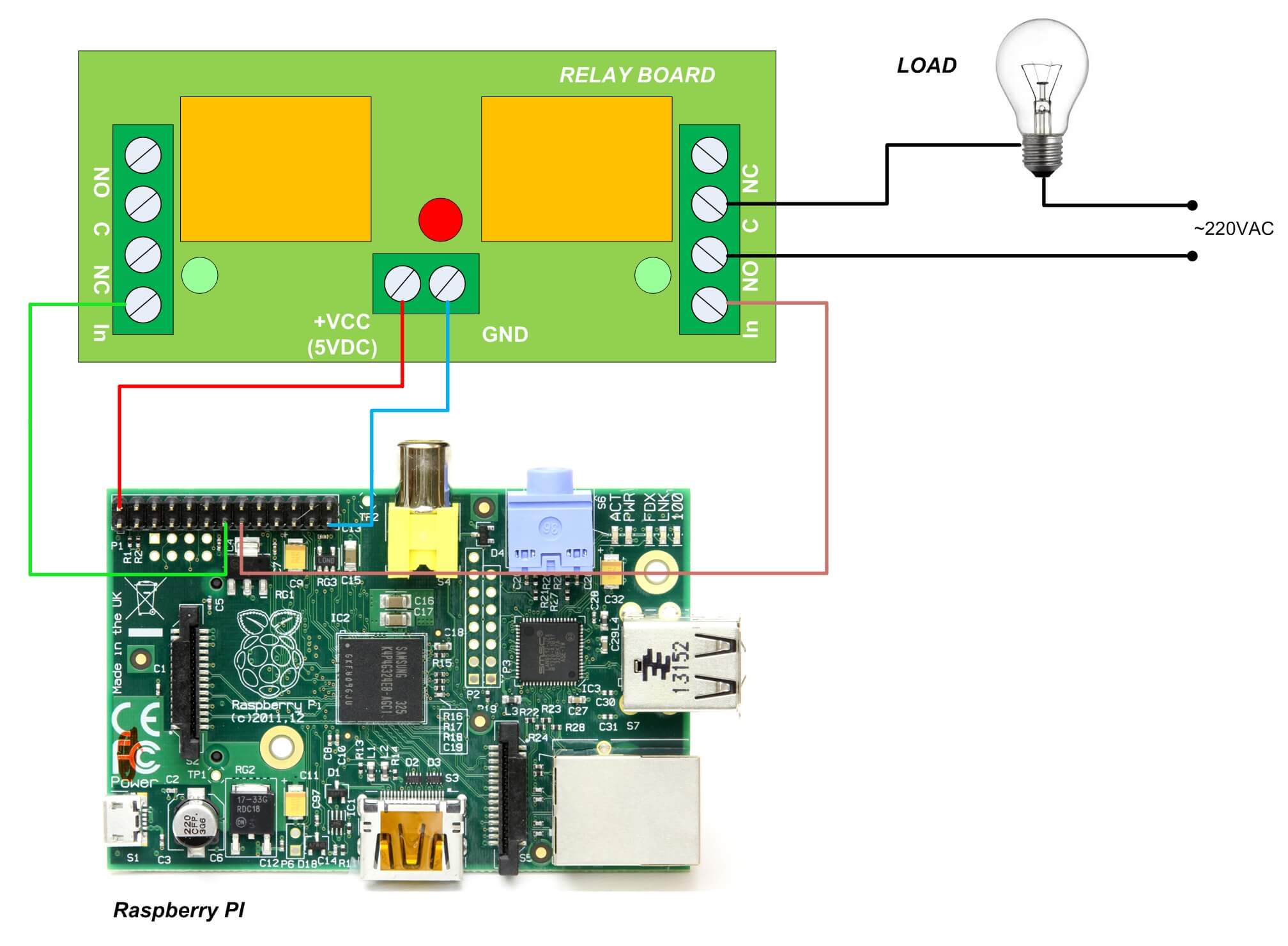
Above is given example for 2 relays only. You can supply either from external power supply source, either from Raspberry PI (however you must consider the maximum allowed current draw from Pasrberry PI in this case)
Useful links:
 Controlling inductive loads - http://denkovi.com/controlling-inductive-devices
General purpose relay
10 Channel Relay Board 5V
For arduino, rpi, avr
-


DIN RAIL Set DAE-DIN1
A DIN Rail set suitable for all our General Purpose Relay Boards and LM35DZ Relay Boards
Price: $3.50 -
10 Channel relay board for your Arduino or Raspberry PI - 12V
<p style="text-align: justify;">A general purpose 10 SPDT channel relay board (power supply 12VDC) for switching high-current electrical loads (both AC and DC) siuch as motors, lights, pumps, contactors and more. With this relay board, any logic-level signal from 3V up to 30V can be used to activate a relay (it may be controlled direclty by microcontroller TTL logic as well). It can be used successfully for example with PIC,AVR,ARM microcontroller, Raspberry PI, Arduino outputs and other.</p>
Price: $41.50 -
10 Channel relay board for your Arduino or Raspberry PI - 24V
A general purpose 10 SPDT channel relay board (power supply 24VDC) for switching high-current electrical loads (both AC and DC) siuch as motors, lights, pumps, contactors and more. With this relay board, any logic-level signal from 3V up to 30V can be used to activate a relay (it may be controlled direclty by microcontroller TTL logic as well). It can be used successfully for example with PIC,AVR,ARM microcontroller, Raspberry PI, Arduino outputs and other.
Price: $41.50


