Cart is empty.
.png)


Configuration/control/monitor utility for IP controller DAEnetIP1
Please note this software is not anymore supported, it is replaced now by DRM Software v3
|
|
- General overview
- What can DAEnetIP1 Manager do
- Who can use DAEnetIP1 Manager
- List with currently supported DAEnetIP1 devices
- Current version download
- DAEnetIP1 Manager system requirements
- DAEnetIP1 Manager installation guide for Windows
- User interface
- Log in
- Port JP1
- Port JP2
- Relay Control
- ADC
- SNMP Settings
- Admin
- Update
DAEnetIP1 Manager is SNMP v1 configuration/control/monitor utility for DAEnetIP1. It supports many functions of the controller but not all. In this page they are described all the features of current version. It works as sending/receiving snmp requests to the target DAEnetIP1 controller.
With this software you are able to:
- Monitor DAEnetIP1 JP1, JP2, JP3, JP4 ports
- Configure snmp and network settings
- Make DAEnetIP1 firmware update
- Simple handling of traps
DAEnetIP1 Manager may be used by anyone who has at least one of DAEnetIP1 devices from the current version supported list.
List with currently supported DAEnetIP1 devices
|
Order number
|
Device name and link
|
| DAEnetIP1 | DAEnetIP1 |
| DAEnetIP1 + DAE-RB/Ro4_v2 | Internet/Ethernet Four Channel Relay Board |
| DAEnetIP1 + DAE-RB/Ro8-12V | Internet/Ethernet Eight Channel Relay Board - ver.1 |
| DAE-PB-RO12/DI8/AI8 + DAEnetIP1 | SNMP and Web based Data Acqusition I/O Module |
|
Version
|
Release date
|
Download links
|
Details
|
| 1.3 | 12.04.2011 | SNMP RW/RO Community access removed (no longer suppoted by SNMP, only via WEB). | |
| 1.2 |
09.04.2011
|
Temperature measurement removed, web username/password removed, added JP1and JP3 inverse function, fixed MAC bug reading, JP2 description writing fixed. | |
| 1.0 | 01.02.2010 |
The first version |
DAEnetIP1 Manager system requirements
Operating systems: Windows XP, Windows Vista, Windows 7
Java Virtual Machine: Yes. The last version is included from the release date in the installation setup file
DAEnetIP1 Manager installation guide for Windows
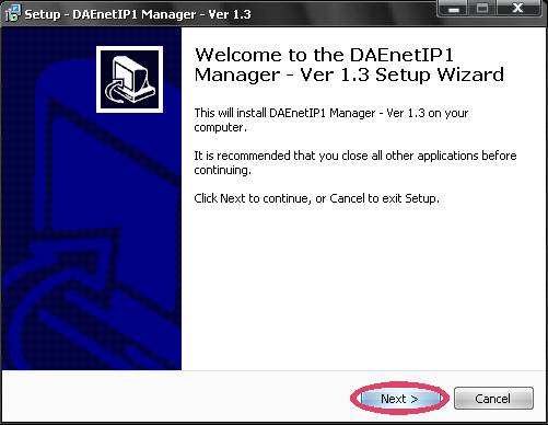
To get installed DAEnetIP1 Manager on your PC the only thing you need to do is to download and run the installation file DAEnetIP1Manager.exe. The whole installation takes several minutes. Here are the steps you should go through the installation:
1) Download DAEnetIP1Manager.exe and run it.
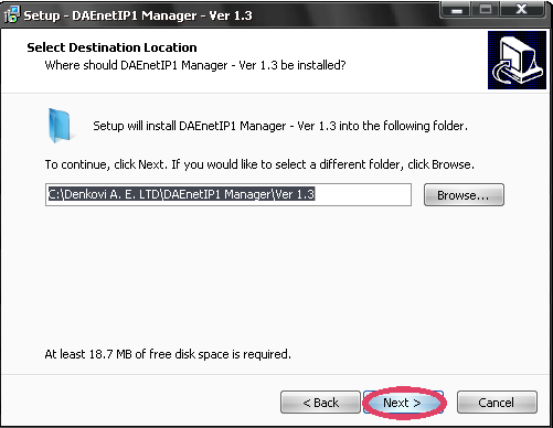
2) Select the place you would like to be installed DAEnetIP1 Manager. It is recommend to install it on drive that is different from C:\
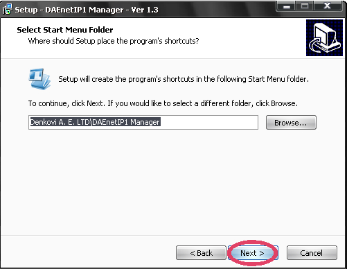
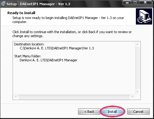
3) Setup will create icons on your start menu.
4) Install.
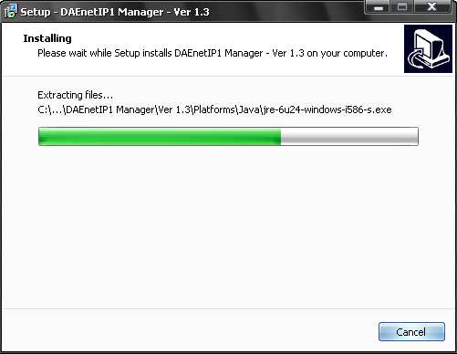
5) Installation progress.
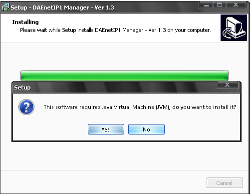
6) You will be asked if you have JVM (Java Virtual Machine). If your PC does not have any JVM installed, you need to click "Yes" and follow the steps that JVM installation window will guide throug. If you have already JVM click "No". If you have already JVM and click "Yes" to install it - don't worry. Nothing will be wrong, just will take several more minutes to update your JVM to the latest version.
7) Finish the installation.
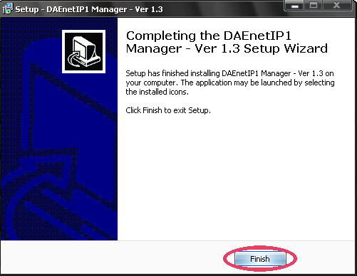
8) You may find the DAEnetIP1 Manager icon on your desktop.
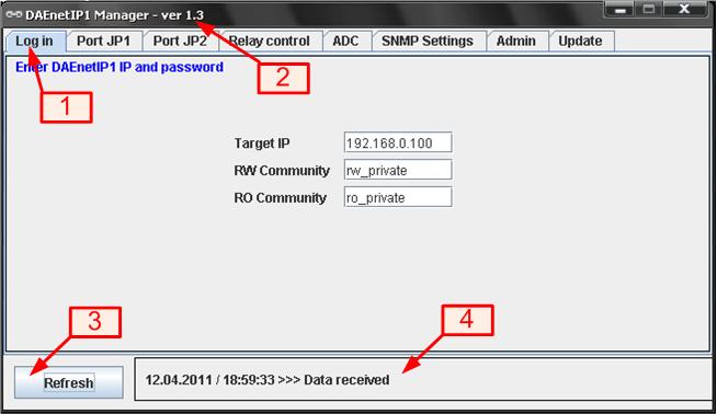
User interface
1) Main tab. Switches the different sections.
2) DAEnetIP1 Manager version. The current version of this copy.
3) Button 'Refresh'. This is button that reads DAEnetIP1 parameters and tests if there is connection.
4) Message panel. In this panel are displayed all messages. Also when trap is received it shown here. Time stamp is at the begining of the message.
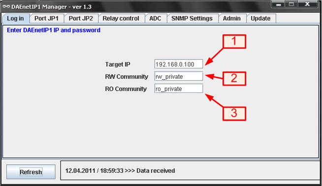
Log-in screen
1) Target IP. IP address of target DAEnetIP1 module
2) RW Community. This is the community for read/write via SNMP requests.
3) RO Community. This is the community for read-only via SNMP requests. It is used also for receiving TRAPS.
Note that to save 'Target IP', 'RW Community' and 'RO Community' you must click button 'Refresh' first. 'RW Community' and 'RO Community' can not be accessed via DAEnetIP1 Manager, only via WEB so firstly you need to get them via Web and enter them in DAEnetIP1 Manager.
DAEnetIP1 JP1 is 8 bit digital output port. When there is JP1 pin level change DAEnetIP1 sends trap message to the given trap servers.
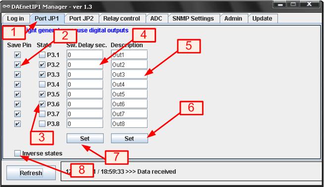
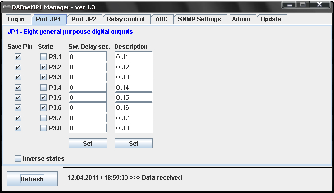
Port JP1 screen
1) Port JP1 tab
2) Save Pin. Save current pin settings in the EEPROM (see switch delay)
3) State. Current pin state. Checked means that JP1 pin output is 3.3V (logical 1). Not checked means that JP1 pin output is 0V (logical 0)
4) Sw. Delay sec. Delay in seconds for reverts pin state. Must be zero, before saving pin state!
4.1) If Sw. Delay sec. is with value between 1 and 254, if the pin state was changed then the pin will revert in the original state after defined delay.
4.2) If Sw. Delay sec. is set, after DAEnetIP1 bootup the pin will change his state after delay.
4.3) Pin with Sw. Delay sec. 0, will immediatly change his state without revert to original.
5) Description. Up to 15 symbols.
6) Button 'Description Set'. Sends 8 snmp requests for saving the eight description fileds in DAEnetIP1.
7) Button 'Sw. Delay sec. Set'. Sends 8 snmp requests for saving the switch delay fileds in DAEnetIP1.
8) Inverse states. Some of our relay boards connected to DAEnetIP1 JP1 port have inverse logic. That is why we've added this extra function. When this checkbox is:
8.1) Checked (1), the controlling/reading of JP1 is inverse. This means when State is checked (1), JP1 pin level is 0V. When State is unchecked (0), JP1 pin level is 3.3V.
8.2) Checked (2), the controlling/reading of JP1 is inverse. This means when State is checked (0), JP1 pin level is 0V. When State is unchecked (1), JP1 pin level is 3.3V.
Not that there is not SNMP command for this function, it is only for more confortable interface.
JP2 is 8 bit digital input/output port. When there is JP2 pin level change DAEnetIP1 sends trap message to the given trap servers.
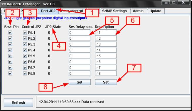
Port JP2 screen
1) Port JP2 tab
2) Save Pin. Save current pin settings in the EEPROM (see switch delay)
3) Control JP2. When it is checked, this JP2 pin works as input. If it is unchecked - works as output.
4) JP2 State. Current pin state level. Checked means that JP2 pin output level is 3.3V (logical 1). Not checked means that JP2 pin output level is 0V (logical 0)
5) Sw. Delay sec. Delay in seconds for reverts pin state. Must be zero, before saving pin state!
5.1) If Sw. Delay sec. is with value between 1 and 254, if the pin state was changed then the pin will revert in the original state after defined delay.
5.2) If Sw. Delay sec. is set, after DAEnetIP1 bootup the pin will change his state after delay.
5.3) Pin with Sw. Delay sec. 0, will immediatly change his state without revert to original.
6) Description. Up to 15 symbols.
7) Button 'Description Set'. Sends 8 snmp requests for saving the eight description fileds in DAEnetIP1.
8) Button 'Sw. Delay sec. Set'. Sends 8 snmp requests for saving the switch delay fileds in DAEnetIP1.
DAEnetIP1 JP3 is 4 bit digital output port. It is also called Relay Port because DAE-RB/Ro4_v2 relay card is connected to this port.
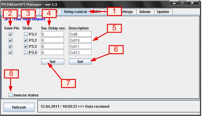
Port JP3 (Relay Control) screen
1) Port JP3 tab (Relay Control tab)
2) Save Pin. Save current pin settings in the EEPROM (see switch delay)
3) State. Current pin state. Checked means that JP3 pin output is 3.3V (logical 1). Not checked means that JP3 pin output is 0V (logical 0)
4) Sw. Delay sec. Delay in seconds for reverts pin state. Must be zero, before saving pin state!
4.1) If Sw. Delay sec. is with value between 1 and 254, if the pin state was changed then the pin will revert in the original state after defined delay.
4.2) If Sw. Delay sec. is set, after DAEnetIP1 bootup the pin will change his state after delay.
4.3) Pin with Sw. Delay sec. 0, will immediatly change his state without revert to original.
5) Description. Up to 15 symbols.
6) Button 'Description Set'. Sends snmp requests for saving the description fileds in DAEnetIP1.
7) Button 'Sw. Delay sec. Set'. Sends snmp requests for saving the switch delay fileds in DAEnetIP1.
8) Inverse states. Some of our relay boards connected to DAEnetIP1 JP3 port have inverse logic. That is why we've added this extra function. When this checkbox is:
8.1) Checked (1), the controlling/reading of JP1 is inverse. This means when State is checked (1), JP3 pin level is 0V. When State is unchecked (0), JP3 pin level is 3.3V.
8.2) Checked (2), the controlling/reading of JP1 is inverse. This means when State is checked (0), JP3 pin level is 0V. When State is unchecked (1), JP3 pin level is 3.3V.
Not that there is not SNMP command for this function, it is only for more confortable interface.
JP4 is 8 channel x 10-bit ADC input port(0 - 2.5 VDC) with 2.5VDC refferent voltage. When some ADC input crosses given high/low threshold may be done the following: 1) a trap message may be sent. 2) JP1 pin state may be changed. 3) JP3 pin state may be changed.
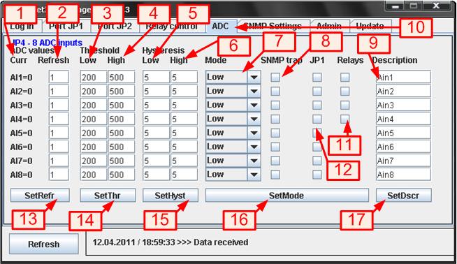
Port JP4 (ADC Port) screen
1) Current analog input level. This is current value measured from the adc channel ( 0 - 1023)
2) Refresh. Read frequency (1=100ms)
3) Threshold Low - low voltage limit
4) Threshold High - high voltage limit
5) Hysteresis Low - low voltage hysteresis
6) Hysteresis High - high voltage hysteresis
7) Mode. Checkbox with adc modes.
7.1) Low. If the measured value is under LT (low threshold) the corresponding digital output (JP1 or/and JP3(Relays) ) becomes 0. Over it - 1.
7.2) High. If the measured value is over HT (high threshold) the corresponding digital output (JP1 or/and JP3(Relays) ) becomes 1. Over it - 0.
7.3) Low/high. The measured value under LT corresponding digital output becomes 0. Between LT and HT - 1. Over HT - 0.
7.4) Acc. The measured value falls under LT, corresponding digital output becomes 0. Digital output becomes 1 above HT.
8) SNMP trap. DAEnetIP1 sends SNMP trap message when the measured ADC value crosses given high/low threshold.
9) JP1. Corresponding JP1 pin state is changed when the measured ADC value crosses given high/low threshold.
10) SNMP trap. DAEnetIP1 sends SNMP trap message when the measured ADC value crosses given high/low threshold.
11) Relay. Corresponding relay pin state is changed when the measured ADC value crosses given high/low threshold.
12) Description - ADC channel description.
13) Button 'SetRefr'. Sets all refresh values
14) Button 'SetThr'. Sets all threshold values
15) Button 'SetHyst'. Sets all hysteresis values
16) Button 'SetMode'. Sets all adc channels modes
17) Button 'SetDescr'. Sets all description values
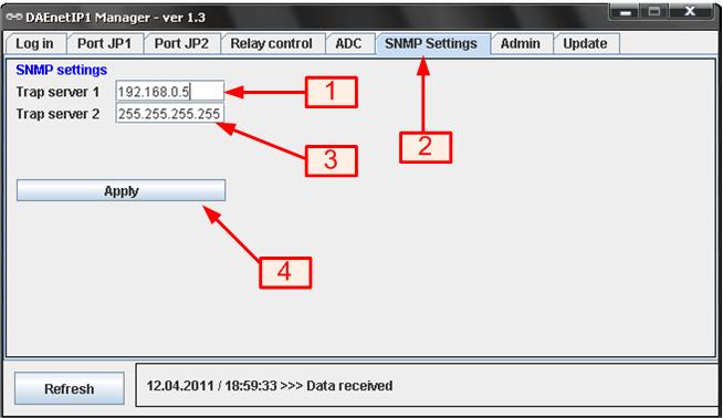
SNMP Settings screen
1) Trap Server 1. This is the first trap server for DAEnetIP1. It must be 255.255.255.255 if it is not used
2) SNMP Settings tab.
3) Trap Server 2. This is the second trap server for DAEnetIP1. It must be 255.255.255.255 if it is not used
4) Button 'Apply' - Save the settings
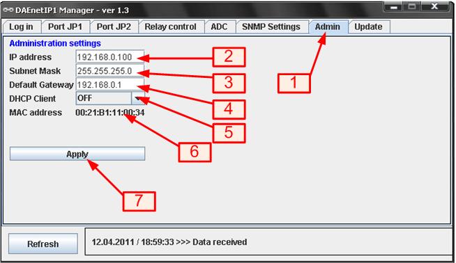
Admin screen
1) Admin tab.
2) IP Address. IP address of the module
3) Subnet Mask. Network mask of the module
4) Default Gateway.
5) DHCP Client - ON/OFF
6) Mac address - the mac address of the module. Can not be changed.
7) Button 'Apply' - Save the settings
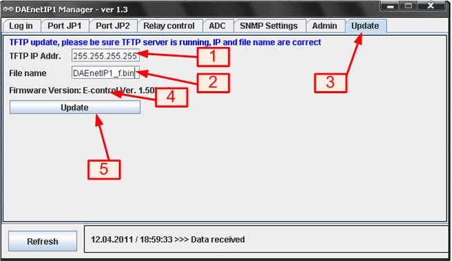
Update screen
1) TFTP IP Addres. The IP address of the TFTP server for DAEnetIP1 firmware update.
2) File name. DAEnetIP1 firmware file name.
3) Update tab.
4) Firmware version. The current firmware version
5) Button 'Update'. When it is pressed, updating the firmware starts. The application sends SNMP firmware update request to the DAEnetIP1 controller. You need to wait about minute for finishing the update. Be sure that TFTP server is started, IP address is correct and file name is the same, otherwise DAEnetIP1 firmware won't be loaded correctly!


