Cart is empty.
.png)
.png)


This page helps you with tips and tricks how can be avoided electromagnetic interferences while controlling inductive loads with our relay boards
The problem is while controlling inductive loads the relay board stops working ("get stucked", "freezed") and usually the only solution is to reconnect the USB cable (if this is USB relay board) or even to reset from power supply. Usually this happens during the first several toggles but may occure in hours as well. This may appears mostly for the USB relay boards but it is possible also to be valid for the other relay boards (with ethernet interface for example). Well known fact is that such inductive loads may be:
- Motors
- Solenoids
- Transformers
- Big Power Relays
- Contactors
- Big lamps
The reason is that while switching ON/OFF, there is electromagnetic interference passed through the relay comming from the inductive load stright to the relay board interface chipset.
The solution
The solution of the problem usually is adding simple film capacitor (induction suppression capacitor) in paralell of the load. The purpose of this capacitor is to absorb the high voltages generated by inductive loads, blocking them from the contacts of the relays. Without this capacitor, the lifespan of the relay will be reduced as well. Induction can be so severe that it electrically interferes with the microprocessor logic of our controllers, causing relay banks to shut themselves down unexpectedly or freeze. Thats why in the case of USB relay boards, customers may experience loss of communications until the device is reconnected to the USB port or even reset the power supply. Bellow it is given the electrical diagram of connection:
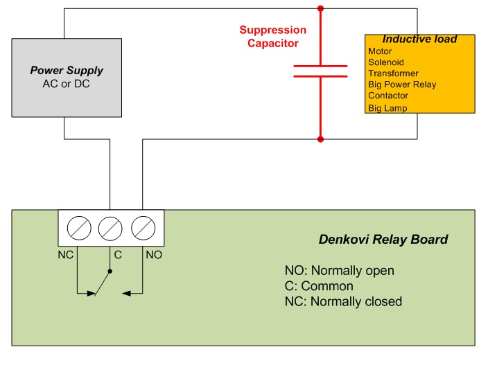

The capacitor is attached as close to the relay board as possible and it is connected in parallel of the controlled load. Induction suppression capacitors are NOT polarized, and may be used in both AC or DC applications.
Which capacitors are suitable?
Choosing the correct induction suppression capacitor is simply a matter of choosing the maximum voltage requirement of the controlled inductive load. You can choose the capacitor to be with higher voltage than the controlled load. The capacitor value of 0.47uF – 0.68uF usually is ok. For example bellow are shown search results of such capacitors:
Resistive loads
Unlike inductive loads, resistive loads such a incandescent lights and element heaters (without a fan), do NOT require an induction suppression capacitor, and will NOT benefit from its use.
ATTENTION: USB MODULES
USB communication usually is sensitive to inductive loads. USB establishes high-speed communications with the motherboard of your PC. If an error is presented on the USB port, the motherboard of your computer will disconnect the device from the operating system. In the case of USB relay controllers, you will lose communications until the device is unplugged from the USB port and plugged back in. When working with USB communications in combination with inductive loads, it is absolutely essential that induction suppression capacitors are used to help prevent loss of communications. Even with these capacitors in place, the possibility does exist that capacitors will not suppress enough induction to prevent periodic communications loss. Extensive testing is required in these applications. If problems persist, other communications mechanisms must be considered.
ATTENTION: SHARING POWER SUPPLIES WITH INDUCTIVE LOADS
The power supply used to supply power to denkovi devices should not be shared with inductive loads. For instance, you should never use a single power supply to power a denkovi relay board (controller) and a 12V DC Motor. Doing so will introduce extremely high-voltage spikes that may damage the logic and power regulation portions of denkovi devices, and in many cases, the denkovi device will NOT BE REPAIRABLE. The only known exceptions to this warning are customers who are working in automotive or other battery-powered applications where induction is naturally suppressed by integrating a large battery into the design. Additional filtering circuits may also be used to clean the power supply before entering the denkovi device, provided they are properly designed to work with your particular inductive load. Induction suppression capacitors may assist in the filtering of the power supply, but more study is required to determine their effectiveness at cleaning the power supply before it enters the denkovi device.
Additionally if the Induction suppression capacitors does not help you can try to separate the inductive load power supply from the computer (and denkovi device) power supply as far as possible each others.
ATTENTION: HIGH VOLTAGE WARNING
Please Note: THESE CAPACITORS WILL STORE DANGEROUSLY HIGH VOLTAGES FOR SHORT PERIODS OF TIME. BEFORE HANDLING, SHORT CIRCUIT THE CAPACITOR OUTPUTS AFTER USE.
Last update: 18 June 2014


