Cart is empty.
.png)


This page is about how to connect analog sensors to DAEnetIP2 ethernet controller. In this way it is possible to measure different analog values like temperature, humidity, distance and control electrical device or send traps based on the meausred values.
- What is the purpose of this web page?
- For which devices is this tutorial?
- DAEnetIP2 ADC port (P6)
- Connecting LM35DZ (temperature sensor)
- Connecting LM335 (temperature sensor)
- Connecting HIH-4000 (humidity sensor)
- Connecting GP2y0A21YK (distance sensor)
- Connecting TSL250R (light to voltage optical sensor)
What is the purpose of this web page?
This article main aim is to help you in projects where a various analog sensors must be connected to the inputs of our DAEnetIP2 controllers or modules based on them. In most of the cases, our DAEnetIP2 controller can work with analog sensors like LM35DZ (temperatre), HIH-4000 humidity and so on... Some of these sensors are with linear voltage output and some of them not. In the first case, their value can be easily calculated with single equation (linearization by 2 points). In the second case, however this is not possible with this method but still such sensors can be used for triggers(to switch relay, send snmp trap). Here, we've put some example schematics how to connect such sensor to DAEnetIP2 controller.
We have created and small MS Excel file, which can help you to calculate tasks like:
- How to convert ADC units into sensor value (°C,m,%RH....). For example the browser showings of the ADC are in units (0-1023);
- How to convert sensor value into ADC units. For example when you want to set the low/high threshold but you know the sensor value is °C;
- Solve linearization by two points (which is required in software applications, where the ADC value can displayed directly in units like °C,m,%RH and so on); For example some applications require to enter sensor value in °C at 0 units and sensor value at 1024 unuts. This file will help you to solve them.
- Create custom software application showing ADC values in units like °C,m,%RH and so on;
For which devices is this tutorial ?
This tutorial may be useful for all customers that have our devices based on DAEnetIP2 controller.
|
Order number
|
Device name and link
|
| DAEnetIP2 | DAEnetIP2 |
| DAEnetIP2 + DAE-RB/Ro2-12V | Internet/Ethernet 2 Channel Relay Board |
| DAEnetIP2 + DAE-RB/Ro16-12V | Internet/Ethernet 16 Channel Relay Board |
| DAEnetIP2 + DAE-RB/Ro8-12V | Internet/Ethernet 8 Channel Relay Board |
DAEnetIP2 ADC port is under the name P6. Its location is marked on the image bellow.
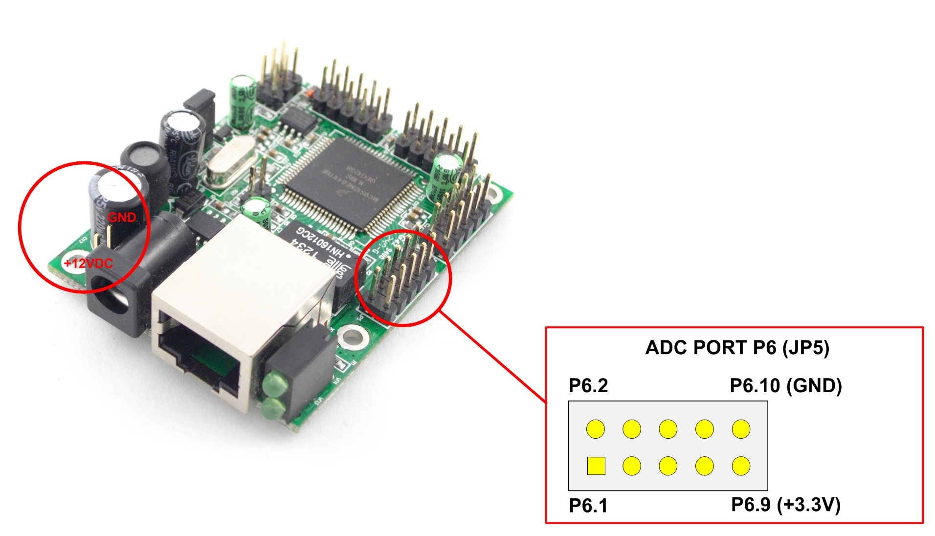
Please note that DAEnetIP2 supports Digital Filter function for better ADC measurement and avoid noises. By default is is turned off. To activate it go to Web server -> Setup -> I/O Ports Settings -> Digital Filter for ADC -> Enable.
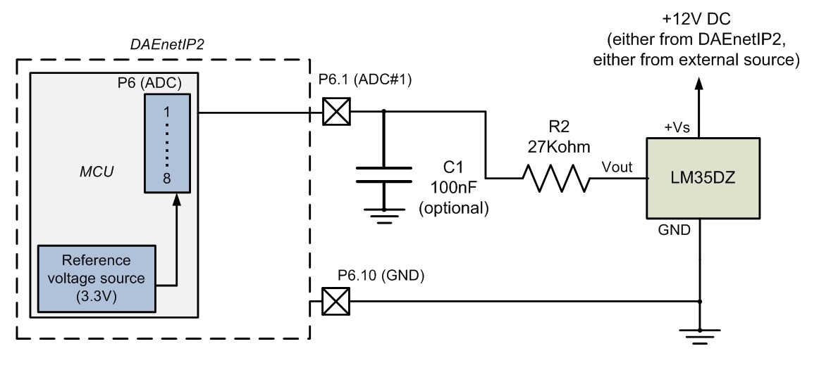
Connecting LM35DZ (temperature sensor) to DAEnetIP2
- LM35DZ can be bought from our web site as well - here.
- LM35DZ is temperature sensor with linear voltage output, which can measure temperatures from 0°C up to 100°C
 LM35DZ datasheet - here
- The schematic is tested with 20 meters flat cable and works well in our laboratory. However for more noisy environment and longer cabel, an extra measurements may be required which are not object of this example.
- The power supply 12VDC for LM35DZ may be taken either from DAEnetIP2 either from external power source;
- The C1 capacitor is optional. It is recommend to be used if the sensor value is not constant.
- Settings for DAEnetIP2 Manager. The software allows to scale the sensor value so it is possible to display the data (and set thresholds) directly in °C. The settings according the schematic above are shown on the next image (to reach this window: DAEnetIP2 Manager->Analog Inputs->Settings button).
.jpg)
- Some data, which may help you:
|
Parameter
|
Value
|
Dimension | Note |
| ADCRes | 10 | bits | The resolution of the ADC |
| Vref | 3.3 | V | The referent voltage of the DAEnetIP2 controller |
| R1 | - | - | Not used in this schematic |
| R2 | 27 | Kohm | See the above schematic (must be connected additionaly) |
| SensMin | 0 | °C | The minimum value of the sensor |
| SensMax | 100 | °C | The maximum value of the sensor |
| SensorRes | 0.01 | V / °C | Sensor resolution, it is taken from the sensor datasheet |
| Vtest | 100 | °C | Testpoint value |
| Vvalue | 1 | V | Output voltage during the testpoint (Vtest) |
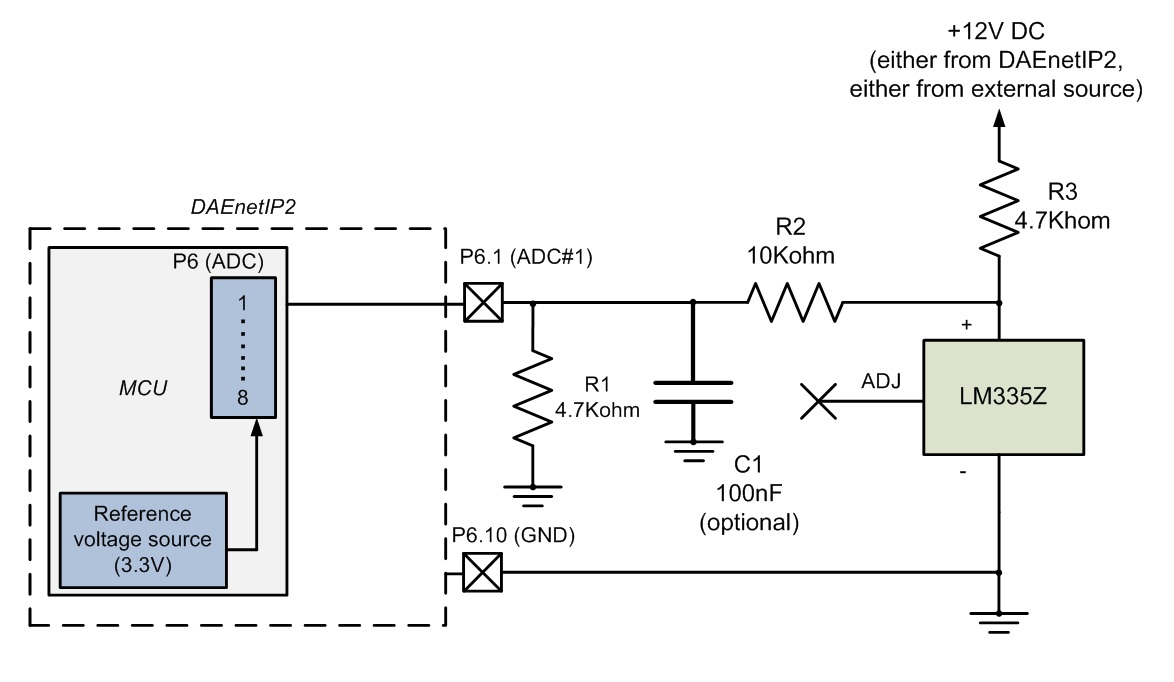
Connecting LM335Z (temperature sensor) to DAEnetIP2
- LM335Z can be bought from our web site as well - here.
- LM335Z is temperature sensor with linear voltage output, which can measure temperatures from -40°C up to 100°C
- LM335Z datasheet - here
- The schematic is tested with 20 meters flat cable and works well in our laboratory. However for more noisy environment and longer cabel, an extra measurements may be required which are not object of this example.
- The power supply 12VDC for LM335Z may be taken either from DAEnetIP2 either from external power source;
- The C1 capacitor is optional. It is recommend to be used if the sensor value is not constant.
- Settings for DAEnetIP2 Manager. The software allows to scale the sensor value so it is possible to display the data (and set thresholds) directly in °C. The settings according the schematic above are shown on the next image (to reach this window: DAEnetIP2 Manager->Analog Inputs->Settings button).
.jpg)
- Some data, which may help you:
|
Parameter
|
Value
|
Dimension | Note |
| ADCRes | 10 | bits | The resolution of the ADC |
| Vref | 3.3 | V | The referent voltage of the DAEnetIP2 controller |
| R1 | 4.7 | Kohm | See the above schematic (must be connected additionaly) |
| R2 | 10 | Kohm | See the above schematic (must be connected additionaly) |
| SensMin | -40 | °C | The minimum value of the sensor |
| SensMax | 100 | °C | The maximum value of the sensor |
| SensorRes | 0.01 | V / °C | Sensor resolution, it is taken from the sensor datasheet |
| Vtest | 25 | °C | Testpoint value |
| Vvalue | 2.98 | V | Output voltage during the testpoint (Vtest) |
- The other sensors from this sieries are LM235 and LM135 - they can also be used with DAEnetIP2 the same way, however please refer to their specification.
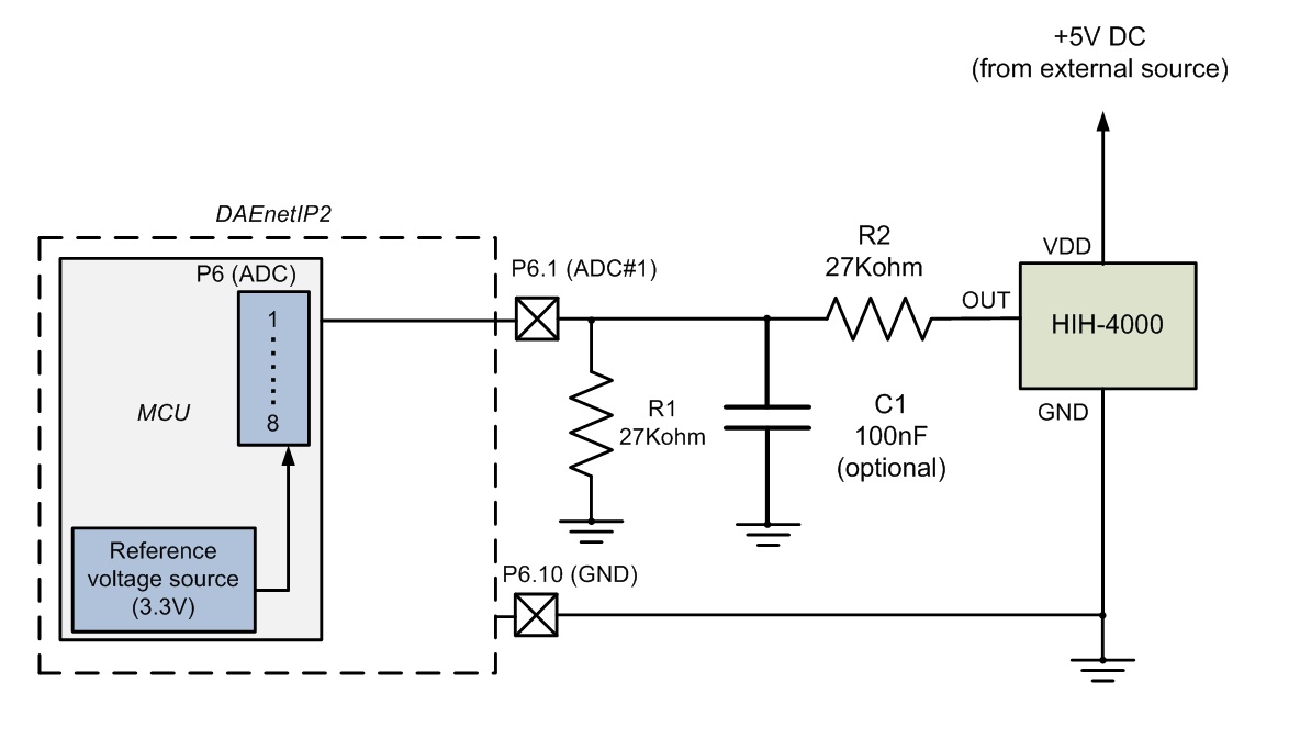
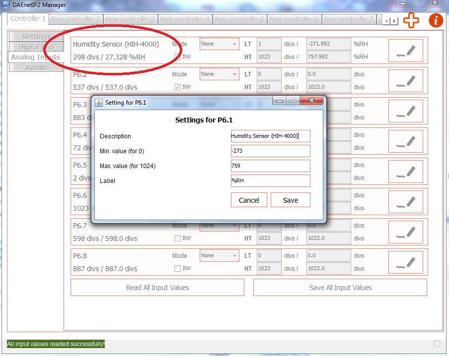
Connecting HIH-4000 (humidity sensor) to DAEnetIP2
- HIH-4000 can be bought from our web site as well - here.
- HIH-4000 is humidity sensor with almost linear voltage output which can measure humidity from 0%RH upto 100%RH.
- HIH-4000 datasheet - here.
- The schematic is tested with 20 meters flat cable and works well in our laboratory. However for more noisy environment and longer cabel, an extra measurements may be required which are not object of this example.
- The power supply 5VDC for HIH-4000 must be taken from external power source.
- The C1 capacitor is optional. It is recommend to be used if the sensor value is not constant.
- Settings for DAEnetIP2 Manager. The software allows to scale the sensor value so it is possible to display the data (and set thresholds) directly in %RH. The settings according the schematic above are shown on the next image (to reach this window: DAEnetIP2 Manager->Analog Inputs->Settings button).
- Some data, which may help you:
|
Parameter
|
Value
|
Dimension | Note |
| ADCRes | 10 | bits | The resolution of the ADC |
| Vref | 3.3 | V | The referent voltage of the DAEnetIP2 controller |
| R1 | 27 | Kohm | See the above schematic (must be connected additionaly) |
| R2 | 27 | Kohm | See the above schematic (must be connected additionaly) |
| SensMin | 0 | %RH | The minimum value of the sensor |
| SensMax | 100 | %RH | The maximum value of the sensor |
| SensorRes | 0.03068 | V / %RH | Sensor resolution, it is taken from the sensor datasheet |
| Vtest | 75.3 | %RH | Testpoint value |
| Vvalue | 3.198 | V | Output voltage during the testpoint (Vtest) |
Connecting GP2Y0A21YK (distance sensor) to DAEnetIP2
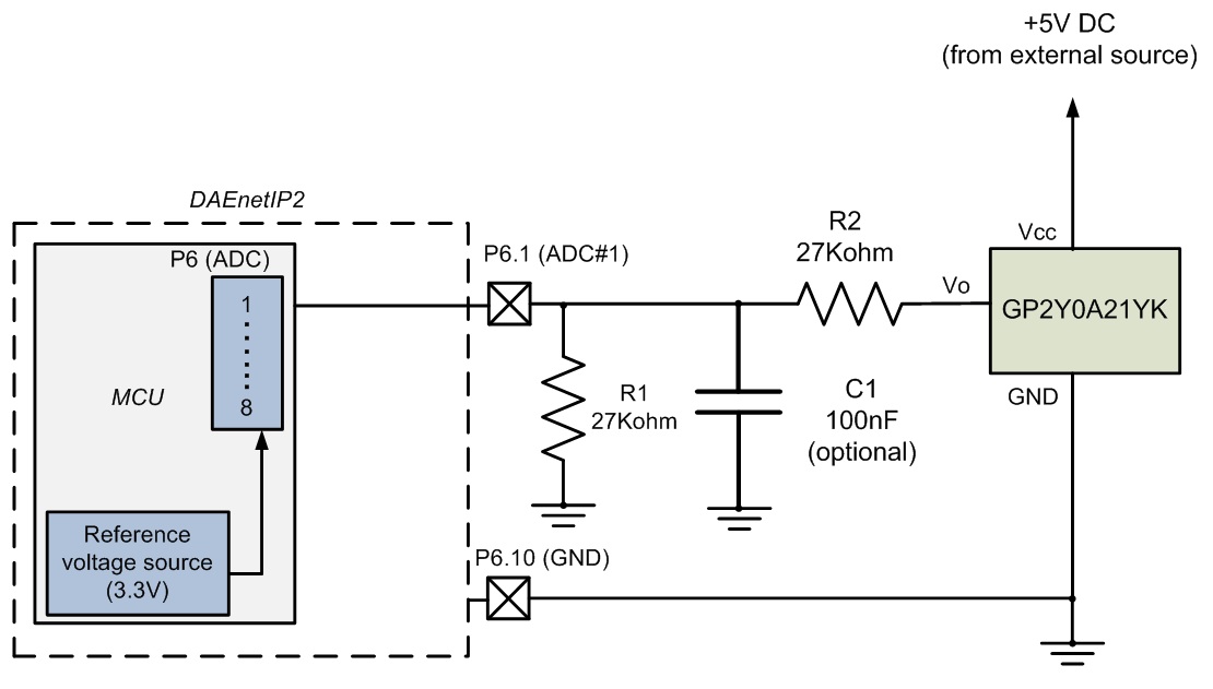
- GP2Y0A21YK can be bought from our webshop as well - here
- GP2Y0A21YK is infrared proximity sensor with non-linearity voltage output. but it can still be used for trigger (to activate relay or send trap).
- GP2Y0A21YK datasheet - here
- The schematic is tested with 20 meters flat cable and works well in our laboratory. However for more noisy environment and longer cabel, an extra measurements may be required which are not object of this example.
- The power supply 5VDC for GP2Y0A21YK must be taken from external power source;
- The C1 capacitor is optional. It is recommend to be used if the sensor value is not constant;
- The R1 and R2 resistors must be connected additionally
- You can use and the other Sharp sensor 20-150cm sensor the same way - http://denkovi.com/infrared-proximity-sensor-20-150cm
Connecting TSL250R (light to voltage optical sensor) to DAEnetIP2
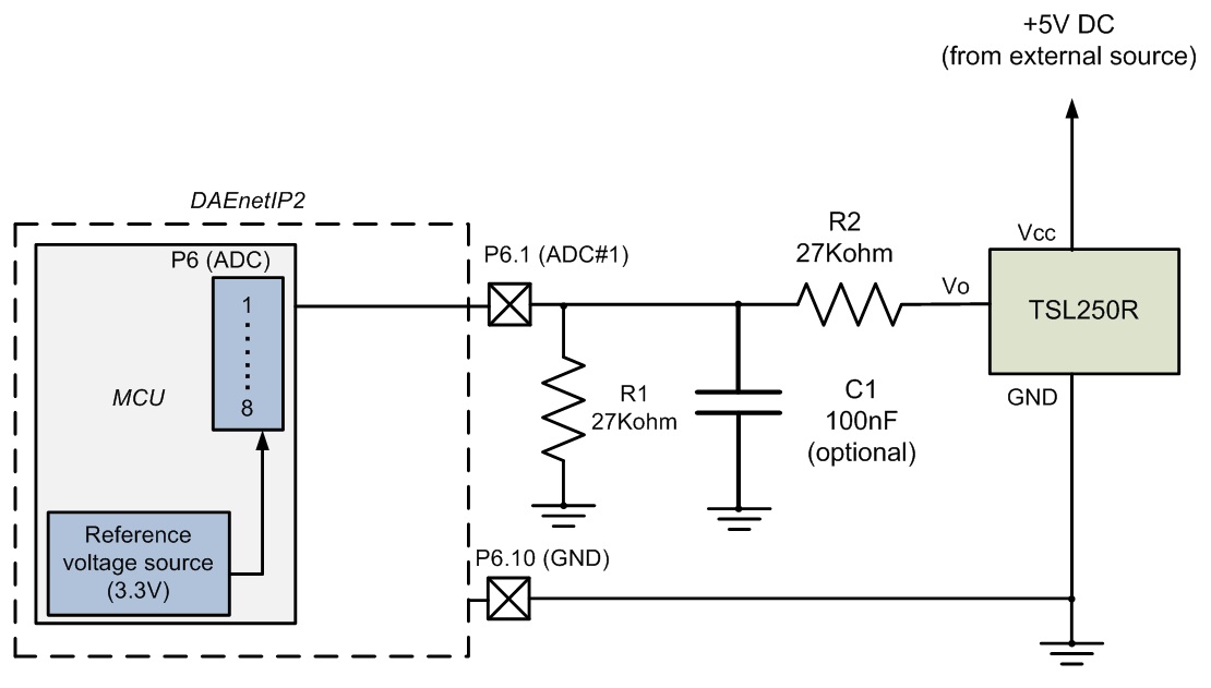
- TSL250R can be bought from our web site as well - here.
- TSL250R is light to voltage optical sensor with non-linearity voltage output but it can still be used for trigger (to activate relay or send snmp trap).
- TSL250R datasheet - here
- The schematic is tested with 20 meters flat cable and works well in our laboratory. However for more noisy environment and longer cabel, an extra measurements may be required which are not object of this example.
- The power supply 5VDC for TSL250R must be taken from external power source;
- The C1 capacitor is optional. It is recommend to be used if the sensor value is not constant.
- The R1 and R2 resistors must be connected additionally
- The other sensors from this sieries are TSL251R and TSL252R - they can also be used with DAEnetIP2 the same way, however please refer to their specification
Last update: 13 May 2014


