
Cart is empty.
 Home
 Products
 Products comparison
 Case Studies
 Customers Projects
 Support




This article explains how to connect analog temperature, humidity, infrared distance and light sensors to the 8-channel 10-bit analog input port (P6) of the DAEnetIP2 v2 Ethernet controller. It includes connection diagrams, resistor and capacitor values, ADC calculations and examples for monitoring and automation.
- What is the purpose of this web page?
- For which devices is this tutorial?
- DAEnetIP2 v2 analog inputs (P6 / JP5)
- Power supply and ADC protection
- ADC values and sensor calculations
- Connecting LM35DZ (temperature sensor)
- Connecting LM335Z (temperature sensor)
- Connecting HIH-4000 (humidity sensor)
- Connecting GP2Y0A21YK (distance sensor)
- Connecting TSL250R (light-to-voltage optical sensor)
What is the purpose of this web page?
The aim of this application note is to help customers connect analog voltage-output sensors to the DAEnetIP2 v2 controller and its relay-board kits. The examples cover LM35DZ and LM335Z temperature sensors, the HIH-4000 humidity sensor, the GP2Y0A21YK infrared distance sensor and the TSL250R light sensor. The analog values may be monitored via the web interface or SNMP and used to trigger digital outputs or SNMP traps.
This application note is based on DAE-AN004: Connecting analog sensors to DAEnetIP2. The newer v2 controller keeps the same 0–3.3 V, 10-bit ADC measuring principle; however, its physical analog connector is JP5 (P6). The resistor dividers and protective resistors in the examples follow the original application note and the v2 user manual.
 DAEnetIP2 v2 User Manual – see Sections 5, 6.3, 6.7, 6.9 and Appendices 10–11 (analog-input protection and sensor connection).
The Custom Calculator Excel file can be used to convert ADC counts to voltage, calculate divider ratios, estimate thresholds and perform two-point linearization in external software. Use Vref = 3.3 V and 10-bit ADC (1024 steps) when entering the DAEnetIP2 v2 parameters.
For which devices is this tutorial?
These examples are useful for DAEnetIP2 v2 and modules/kits based on it, provided that the analog P6 inputs are accessible:
|
Order number
|
Device name and link
|
| DAEnetIP2v2 | DAEnetIP2 v2 Ethernet SNMP controller |
| DAEnetIP2v2 + DAE-RB/Ro2-12V | SNMP 2 Relay Board with DAEnetIP2 v2 |
| DAEnetIP2v2 + DAE-RB/Ro8-12V | SNMP 8 Relay Board with DAEnetIP2 v2 |
| DAEnetIP2v2 + DAE-RB/Ro16-12V | Ethernet 16 Relay Board with DAEnetIP2 v2 |
DAEnetIP2 v2 analog inputs – Port P6 (JP5)
The controller has 8 analog input lines (P6.1 to P6.8), with 10-bit ADC resolution and Vref = 3.3 V. The physical connector is JP5: pins 1–8 are the analog inputs, pin 9 is +3.3 V (Vref) and pin 10 is GND. The connector location and pin numbers are shown below.
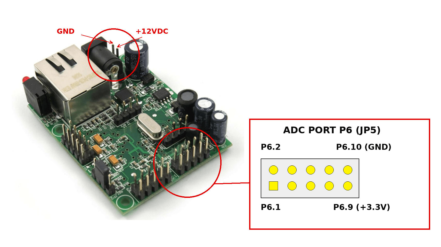
- Important: Do not apply a signal higher than the 0–3.3 V ADC range directly to P6.1–P6.8. The v2 module has no internal pull-up or pull-down resistors on these analog input lines.
- The manufacturer strongly recommends a series protection resistor (approximately 22 kΩ is given as a general example). In the drawings below an existing 27 kΩ or 10 kΩ series resistor provides that function; do not automatically add a second resistor.
- The analog sensor and DAEnetIP2 v2 must have a common GND reference. For each schematic P6.1 is used as an example; P6.2 to P6.8 can be used in the same way.
- The +3.3 V pin on JP5 is not suitable for powering the LM35DZ (minimum 4 V), LM335Z bias circuit with 12 V, or the 5 V sensors described below.
- For noisy readings, use General Settings → Analog Inputs Filter, sec (0–30 seconds), where supported by the installed firmware. A 100 nF input capacitor is shown as an optional example in each connection diagram.
Power supply and ADC protection
The controller itself is powered from 7.5–25 V DC. The original AN004 drawings use +12 V DC for LM35DZ and LM335Z (from the controller’s suitable 12 V supply or an external source) and a regulated +5 V DC supply for HIH-4000, GP2Y0A21YK and TSL250R. This 5 V rail may be provided by a suitable external supply or by an appropriate 12/24 V-to-5 V step-down converter (e.g. TSR 1-2450 or OKI-78SR-5/1.5-W36-C). The conversion hardware is deliberately not drawn; the schematics show the required final sensor supply voltage.
- Do not confuse the 12 V sensor supply or the +5 V sensor supply with JP5 pin 9 (+3.3 V Vref).
- All external sensor supplies must share a common reference with JP5 pin 10 (GND). Follow the datasheet of the selected supply/regulator.
- Do not connect any sensor output directly to P6 without suitable input protection; the current-limiting and voltage-divider resistors shown in the examples are part of the connection.
- C1 is an optional filter capacitor on the ADC side of the protective resistor, usually 100 nF or another suitable value, depending on the sensor and application.
ADC values and sensor calculations
The DAEnetIP2 v2 web interface / SNMP reports a raw analog input level between 0 and 1023. Unlike the smartDEN IP-Maxi example, this controller does not use the same Min/Max temperature scaling screen; engineering units may be calculated in external software such as DAEnetIP2 Manager or a custom application.
VADC ≈ ADC x 3.3 / 1024 (volts); and ADC ≈ VADC x 1024 / 3.3. These nominal conversions use 1024 steps, consistent with 10-bit quantization. Approximately 1 ADC count corresponds to 3.22 mV.
For a 27 kΩ / 27 kΩ voltage divider, VADC ≈ VOUT / 2. For LM335Z with a 10 kΩ upper and 4.7 kΩ lower divider, VADC ≈ VLM335 x (4.7 / 14.7). Exact readings depend on tolerances, calibration, noise and ADC characteristics.
For automation thresholds open Analog Events and use the calculated raw ADC count. Thresholds of 0 and 1023 disable analog-event traps according to the user manual. Calibration should be performed for accurate physical measurements.
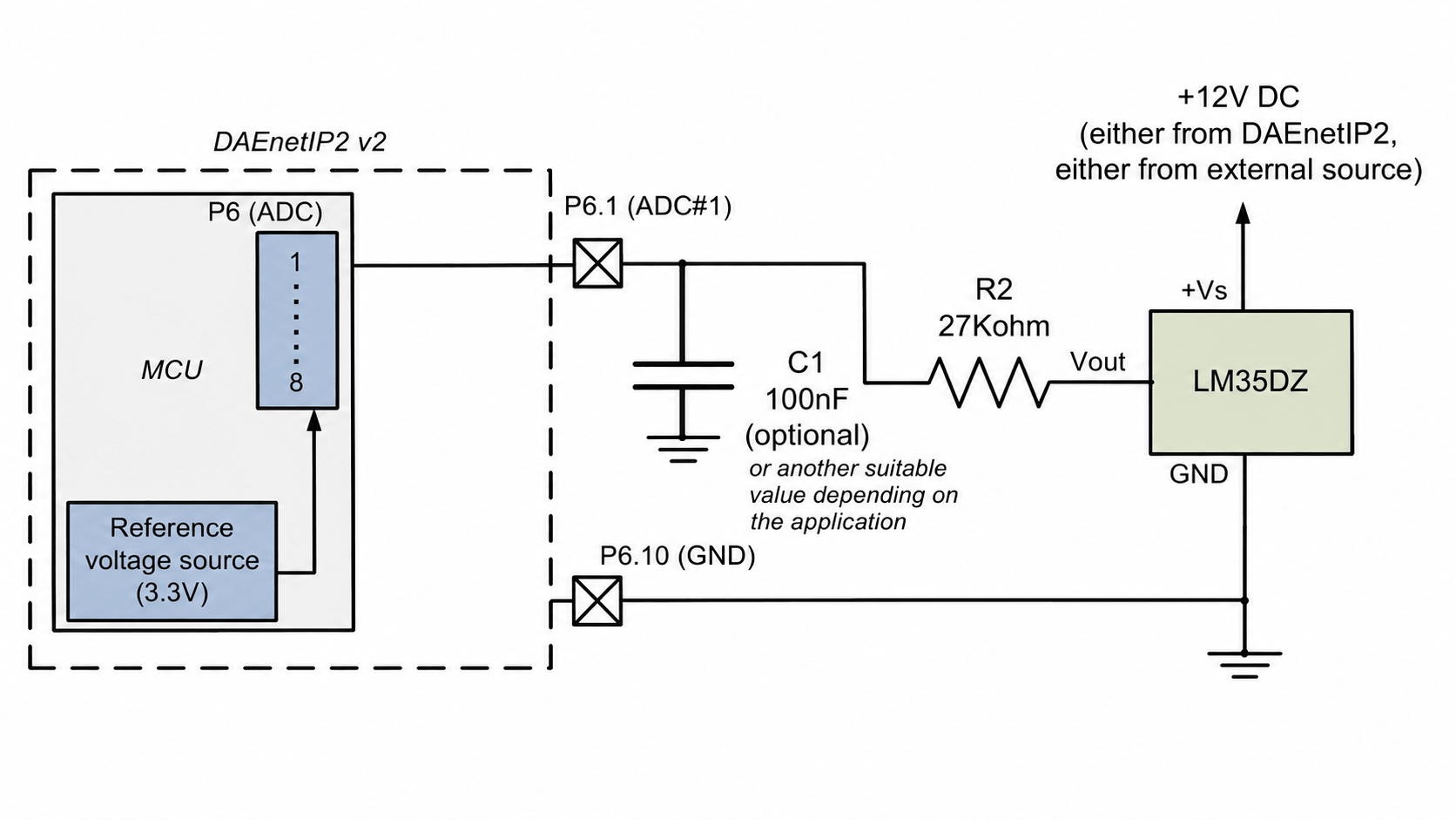
Connecting LM35DZ (temperature sensor) to DAEnetIP2 v2
- LM35DZ can be bought from our webshop as well – here.
- LM35DZ is a temperature sensor with a linear output of 10 mV/°C. With the basic single-supply arrangement the practical example range is 0–100°C.
- LM35DZ datasheet – here.
- Connect +VS to +12 V DC (from the controller’s suitable supply or an external source), GND to JP5 pin 10, and VOUT through R2 = 27 kΩ to P6.1 (JP5 pin 1). R2 is the series input protection resistor.
- C1 = 100 nF (optional) connects between P6.1 and GND, on the ADC side of R2. Another suitable value may be used depending on the application; consider the LM35DZ output-load recommendations in its datasheet.
- The output stays approximately 0–1 V for temperatures 0–100°C; no voltage divider is required. At 25°C the output is approximately 0.25 V, corresponding to roughly 78 ADC counts.
- Example conversion: Temperature (°C) ≈ ADC x 3.3 x 100 / 1024 (nominal; neglecting resistor and ADC input leakage).
- Some data which may help you:
|
Parameter
|
Value
|
Dimension
|
Note
|
| ADCRes | 10 | bits | DAEnetIP2 v2 ADC resolution |
| Vref | 3.3 | V | ADC full-scale reference |
| R2 | 27 | kΩ | External series protective resistor (VOUT to P6.1) |
| SensMin | 0 | °C | Basic LM35DZ single-supply range |
| SensMax | 100 | °C | Basic LM35DZ single-supply range |
| SensorRes | 0.010 | V/°C | Nominal LM35DZ output sensitivity |
| Vtest | 25 | °C | Example temperature |
| Vvalue | 0.250 | V | Sensor output voltage at 25°C |
| ADCtest | ~78 | counts | Nominal 10-bit ADC reading at 0.25 V |
| ADCstep | ~0.322 | °C/count | Nominal temperature increment per ADC count |
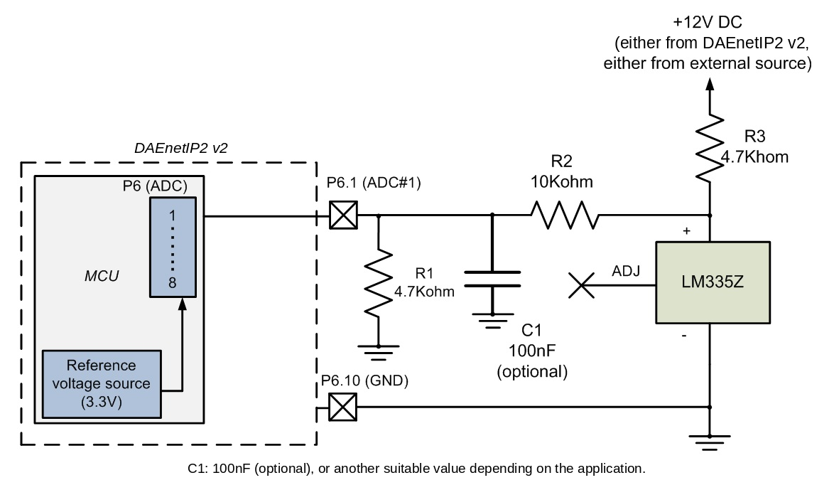
Connecting LM335Z (temperature sensor) to DAEnetIP2 v2
- LM335Z temperature sensor can be bought from our webshop – here.
- LM335Z produces approximately 10 mV/K. The nominal voltage is 2.7315 V at 0°C and 2.9815 V at 25°C.
- LM335Z datasheet – here.
- The sensor needs a bias current. As shown in AN004, R3 = 4.7 kΩ connects +12 V to LM335Z cathode (K). The anode (A) goes to GND, while ADJ is left unconnected in this basic example.
- Because LM335Z output can exceed 3.3 V, R2 = 10 kΩ (between the sensor cathode and P6.1) and R1 = 4.7 kΩ (from P6.1 to GND) form the voltage divider. VADC ≈ VLM335 x 4.7 / 14.7. R2 also provides series input protection; no additional 22 kΩ resistor is included in this schematic.
- C1 = 100 nF (optional) connects between P6.1 and GND. Another suitable value may be used depending on the application and desired filtering.
- The 4.7 kΩ R3 bias resistor is an example for 12 V DC; if another supply voltage is used, recalculate R3 to keep the LM335Z bias current within its datasheet limits.
- At 25°C, VLM335 ≈ 2.9815 V, VADC ≈ 0.9533 V and ADC ≈ 296 counts. Temperature in external software: T(°C) ≈ (ADC x 3.3 / 1024) x (14.7 / 4.7) x 100 − 273.15.
- Some data which may help you:
|
Parameter
|
Value
|
Dimension
|
Note
|
| ADCRes | 10 | bits | DAEnetIP2 v2 ADC resolution |
| Vref | 3.3 | V | ADC reference |
| R1 | 4.7 | kΩ | Lower divider arm (P6.1 to GND) |
| R2 | 10 | kΩ | Series input protection and upper divider arm |
| R3 | 4.7 | kΩ | LM335Z bias resistor (+12 V to cathode K) |
| Divider | 4.7 / 14.7 | ratio | Nominal VADC / VLM335 |
| SensMin | -40 | °C | Example sensor operating range |
| SensMax | 100 | °C | Example sensor operating range |
| SensorRes | 0.010 | V/K | LM335Z sensitivity |
| Vtest | 25 | °C | Example temperature |
| Vvalue | 2.9815 | V | Nominal LM335Z voltage at 25°C |
| VADC | ~0.9533 | V | Nominal voltage at P6.1 after divider |
| ADCtest | ~296 | counts | Nominal ADC reading at 25°C |
| ADCstep | ~1.008 | °C/count | Nominal temperature change per ADC count |
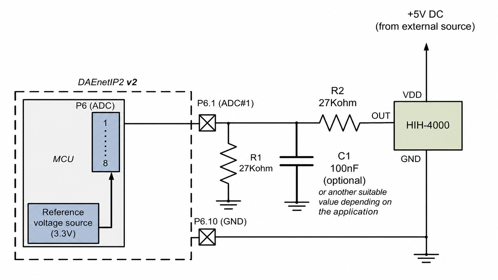
Connecting HIH-4000 (humidity sensor) to DAEnetIP2 v2
- HIH-4000 can be bought from our webshop – here.
- HIH-4000 is a ratiometric humidity sensor for approximately 0–100% RH. With a regulated 5 V supply at 25°C its nominal output is VOUT = 5 x (0.0062 x RH + 0.16).
- HIH-4000 datasheet – here.
- Connect VDD to regulated +5 V, GND to JP5 pin 10, and OUT through R2 = 27 kΩ to P6.1. Connect R1 = 27 kΩ from P6.1 to GND. This divides the sensor voltage by approximately two and protects the ADC input.
- C1 = 100 nF (optional) connects between P6.1 and GND. Another suitable value may be used depending on the application. A stable +5 V supply is important because the HIH-4000 output is ratiometric.
- Example: 50% RH → VOUT ≈ 2.35 V → VADC ≈ 1.175 V → ADC ≈ 365 counts. Use the formula RH(%) ≈ (ADC x 3.3 x 2 / 1024 − 0.8) / 0.031 under nominal 5 V, 25°C conditions.
- When accurate humidity is required, apply sensor calibration and temperature compensation as recommended by the datasheet.
- Some data which may help you:
|
Parameter
|
Value
|
Dimension
|
Note
|
| ADCRes | 10 | bits | ADC resolution |
| Vref | 3.3 | V | ADC reference |
| R1 | 27 | kΩ | Lower arm of output divider |
| R2 | 27 | kΩ | Series input protection, upper divider arm |
| Divider | 1 / 2 | ratio | VADC / VOUT (nominal) |
| Vsupply | 5.0 | V DC | Regulated external supply |
| SensMin | 0 | %RH | Humidity range |
| SensMax | 100 | %RH | Humidity range |
| SensorRes | 0.031 | V/%RH | Nominal VOUT slope at 5 V and 25°C |
| Voffset | 0.800 | V | Nominal VOUT at 0% RH |
| Vtest | 50 | %RH | Example humidity |
| Vvalue | 2.350 | V | Sensor output at 50% RH |
| VADC | 1.175 | V | Voltage after 27 kΩ / 27 kΩ divider |
| ADCtest | ~365 | counts | Nominal ADC reading |
| ADCstep | ~0.208 | %RH/count | Nominal resolution after divider |
Connecting GP2Y0A21YK (distance sensor) to DAEnetIP2 v2
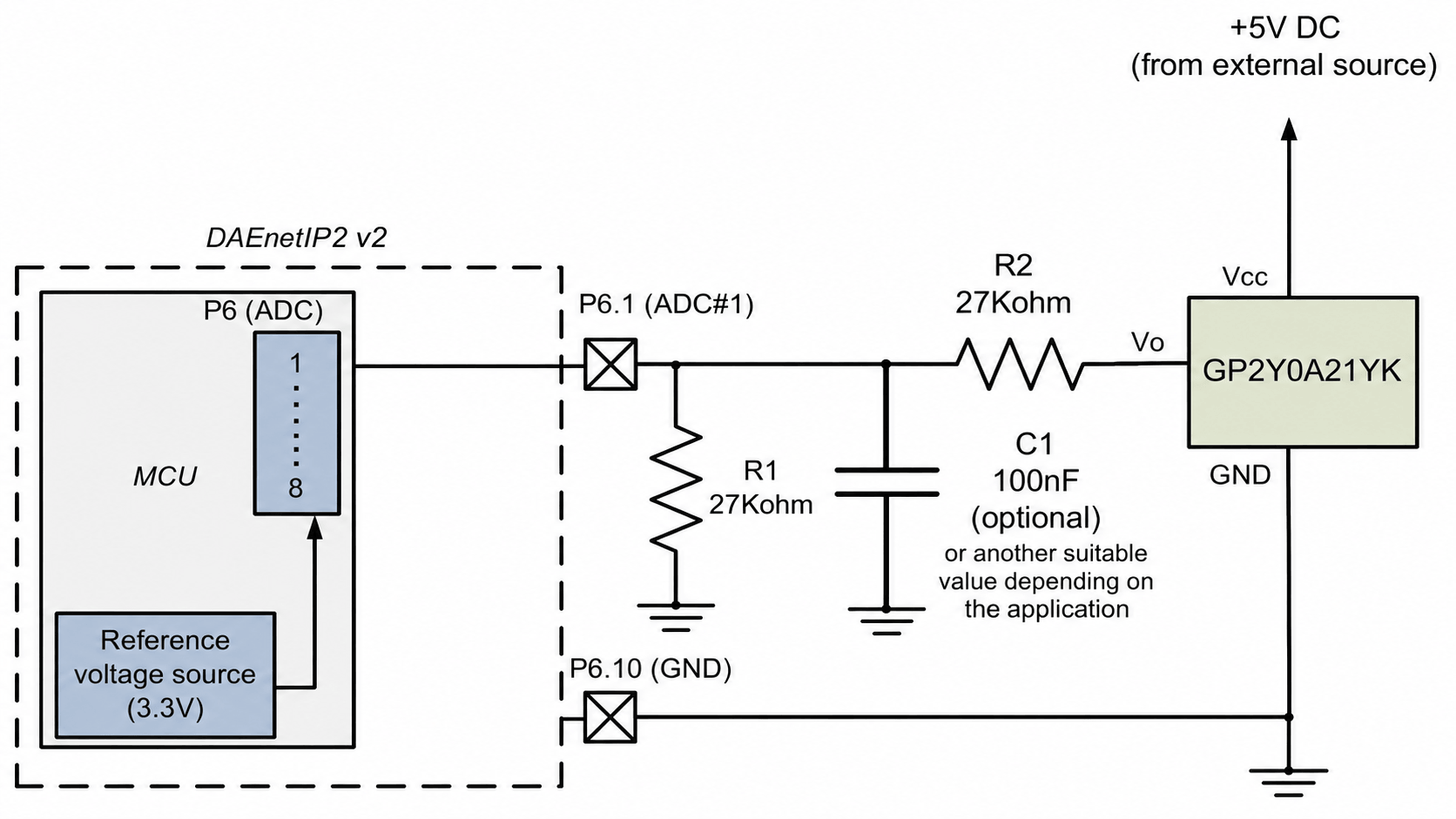
- GP2Y0A21YK can be bought from our webshop – here.
- The Sharp GP2Y0A21YK is an infrared distance sensor with an approximate measuring range of 10–80 cm and a nonlinear voltage-distance characteristic.
- GP2Y0A21YK datasheet – here.
- Power VDD from a regulated +5 V source and connect sensor GND to JP5 pin 10. Connect sensor Vo through R2 = 27 kΩ to P6.1, and R1 = 27 kΩ from P6.1 to GND. The divider limits the ADC voltage to approximately half the sensor output.
- C1 = 100 nF (optional) is connected between P6.1 and GND for input filtering. Another suitable value may be used depending on the application. No additional supply capacitor is shown in the original AN004 connection diagram.
- Typical example only: a sensor voltage of about 3.1 V at 10 cm gives VADC ≈ 1.55 V or 481 counts; about 0.4 V at 80 cm gives VADC ≈ 0.20 V or 62 counts. Readings depend on target reflectivity and conditions.
- The normal two-point linearization of the Custom Calculator is not sufficient to turn the full output range into accurate distance values. Use the ADC readings for proximity thresholds or apply an empirically calibrated lookup table in external software.
- Some data which may help you:
|
Parameter
|
Value
|
Dimension
|
Note
|
| ADCRes | 10 | bits | ADC resolution |
| Vref | 3.3 | V | ADC reference |
| R1 | 27 | kΩ | Lower divider arm |
| R2 | 27 | kΩ | Series protection / upper divider arm |
| Vsupply | 5.0 | V DC | Regulated supply |
| SensMin | 10 | cm | Nominal minimum distance |
| SensMax | 80 | cm | Nominal maximum distance |
| Vnear | ~3.1 | V | Indicative VOUT at 10 cm |
| Vfar | ~0.4 | V | Indicative VOUT at 80 cm |
| ADCnear | ~481 | counts | After 1:2 divider, indicative |
| ADCfar | ~62 | counts | After 1:2 divider, indicative |
| Iavg | ~30 | mA | Typical supply current |
| C1 | 100 | nF | Optional ADC filter |
Connecting TSL250R (light-to-voltage sensor) to DAEnetIP2 v2
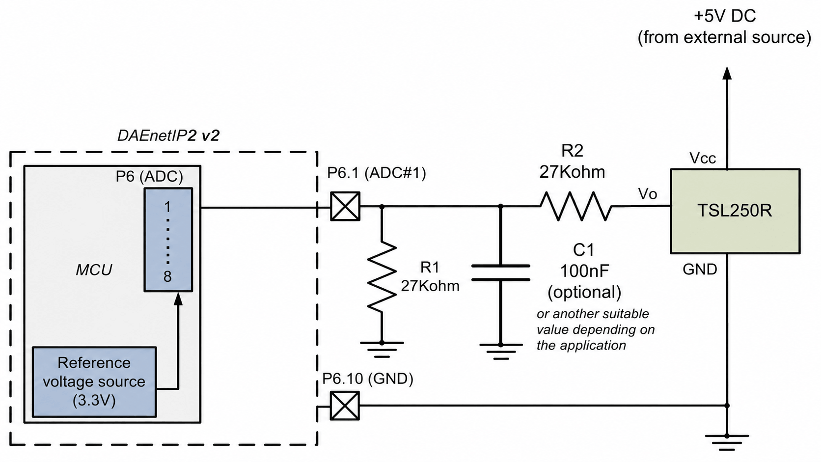
- TSL250R can be bought from our webshop – here.
- TSL250R converts incident light into an analog voltage. The output depends on wavelength and irradiance, so the circuit is most appropriate for relative brightness monitoring or light-triggered relays rather than an uncalibrated lux measurement.
- TSL250R datasheet – here.
- Connect sensor VDD to regulated +5 V, GND to JP5 pin 10, and OUT through R2 = 27 kΩ to P6.1. Install R1 = 27 kΩ from P6.1 to GND. This protects the input and gives VADC ≈ VOUT/2.
- C1 = 100 nF (optional) connects between P6.1 and GND. Another suitable value may be used depending on the application and desired response speed.
- A nominal output example of 2.0 V becomes approximately 1.0 V at the ADC or 310 counts. Use thresholds based on measured values under the actual lighting conditions.
- The related models TSL251R and TSL252R have different sensitivities and require their own datasheet-based calibration.
- Some data which may help you:
|
Parameter
|
Value
|
Dimension
|
Note
|
| ADCRes | 10 | bits | ADC resolution |
| Vref | 3.3 | V | ADC reference |
| R1 | 27 | kΩ | Lower divider arm |
| R2 | 27 | kΩ | Upper divider / series protection |
| Vsupply | 5.0 | V DC | Regulated supply |
| SensorType | Light-to-voltage | – | Optical sensor |
| Vexample | 2.0 | V | Illustrative sensor output; not a lux calibration |
| VADCexample | 1.0 | V | After 1:2 divider |
| ADCexample | ~310 | counts | Illustrative ADC reading |
| ADCstep | ~6.45 | mV sensor output/count | After 1:2 divider |


