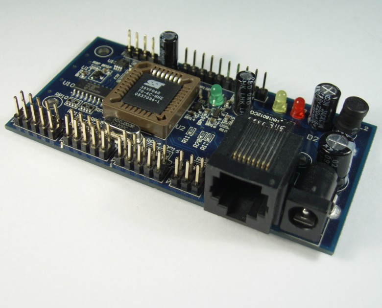
DAEnetIP1 - Internet/Ethernet controller with 8 digital inputs/outputs, 8 digital outputs, 4 relay outputs and 8 ADC inputs
supports SNMP, IP address, MAC address, control via browser and command line
|
|
DAEnetIP1 is multifunctional device for management and control via internet. It could be used for industrial automatization, access control, fire and security systems. It is suitable also for controlling relay boards and tracking different sensors via internet. In some cases it could work as autonomic device - for example like 8 channel relay thermoregulator.
Parameters
- 10/100 Full duplex Ethernet interface
- SNMP v1 TRAP
- SNMP v.1 (snmpget,snmpset)
- WEB interface with authorization
- 8 Digital inputs/outpus
- 8 Digital outputs
- 4 Digital outputs for relays
- 8 Analog inputs (each is with 10 bit resoution)
- Onboard temperature sensor
- Power supply: 12V DC (the middle pin is +12VDC)
- Consumtion: 117mA/12V DC
- Integrated overvoltage protection
- Working temperature from 0 to +40 Celsius
- Storage temperature from -40 to +125 Celsius
- Humidity from 10% to 80% non-condensing
Application examples
- Security and fire alarm systems
- Manual or automatic device restart if event occur
- Management/monitoring for industrial
- Sensor information processing
- Remote electrical devices control
|
DAEnetIP1 connection to the Ethernet network is done with UTP Cat.5 cable with RJ45 connector. Auto MDIX. 8 seconds after power on, the device is ready for work.
Note that in the auction are described the most common features of DAEnetIP1. For full description see the DAEnetIP1 maunal
This auction includes 1 x DAEnetIP1. The shipping via standart post is 6 USD and each next DAEnetIP1 shipping tax is for free !
|
How to connect
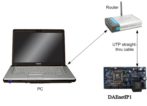
Example of using UTP straight-thru cable |
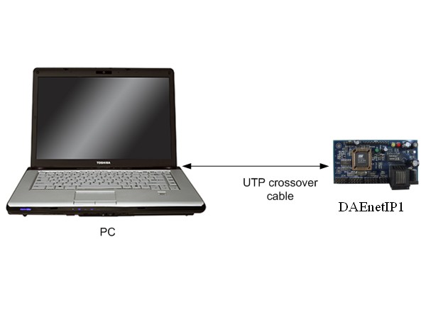
Example of using UTP crossover cable |
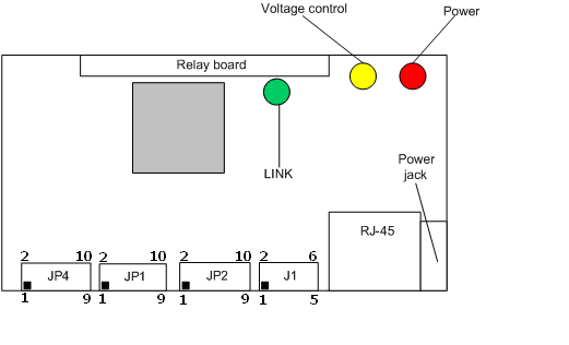
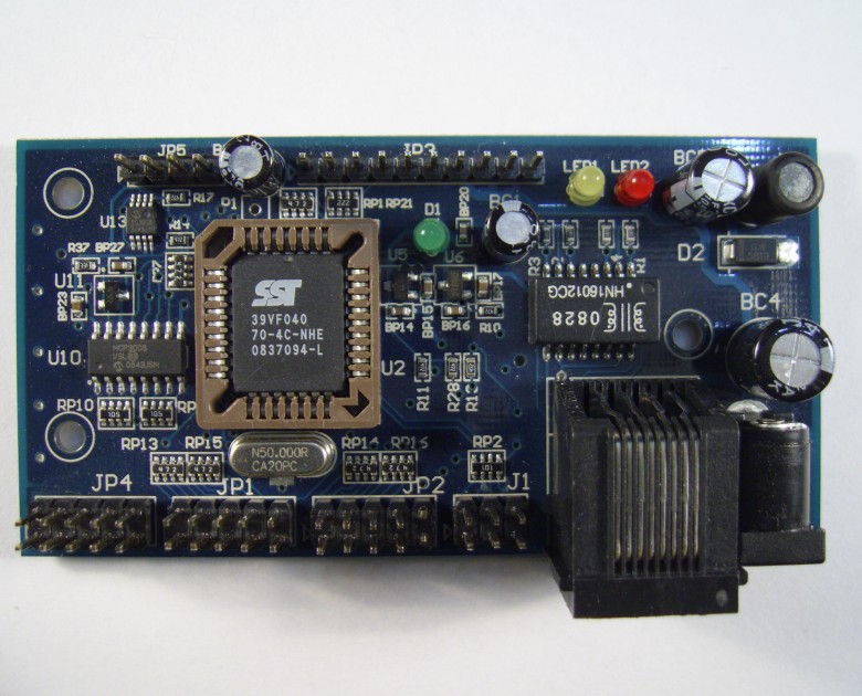
Schematic description
- JP4 – 8 x ADC inputs
- JP1 – 8 x digital outputs (GPO)
- JP2 – 8 x digital I/O (GPIO)
- J1 – Unused
- RJ-45 – UTP cable connector
- Power jack – power connector
- Relay board terminal – 4 digital outputs for relays
LEDs:
- “power” – power 12V DC ready
- “link” – Ethernet activity LED.
- “voltage control” – power 3.3V DC ready
|
|
Default settings
Default IP settings:
IP - 192.168.0.100
Netmask - 255.255.255.0
DG - 192.168.0.1
DHCP – Disabled
WEB username - admin
WEB password - admin
SNMP RW community - private
SNMP RO community - none
How to reset to default settings:
1. From nav-menu -> „Restart“
- Restart – restart the device
- Reset DAEnetIP1 – Restart the device and reset to default values
2.
- power off the device
- place jumper on J1 pin 4 and 6
- power on the device and wait around 10 seconds
- power off the device
- remove the jumper
- power on the device
|
|
I/O ports description
GPIO (JP1)
| Pin No. |
bit |
Func |
direction |
pull-up |
buffer |
| 1 |
0 |
GPO |
OUT |
3v3/4k7 |
100 ohm |
| 2 |
1 |
GPO |
OUT |
3v3/4k7 |
100 ohm |
| 3 |
2 |
GPO |
OUT |
3v3/4k7 |
100 ohm |
| 4 |
3 |
GPO |
OUT |
3v3/4k7 |
100 ohm |
| 5 |
4 |
GPO |
OUT |
3v3/4k7 |
100 ohm |
| 6 |
5 |
GPO |
OUT |
3v3/4k7 |
100 ohm |
| 7 |
6 |
GPO |
OUT |
3v3/4k7 |
100 ohm |
| 8 |
7 |
GPO |
OUT |
3v3/4k7 |
100 ohm |
| 9 |
- |
GND |
- |
- |
- |
| 10 |
- |
3v3 |
- |
- |
- |
|
GPIO (JP2)
| Pin No. |
bit |
Func |
direction |
pull-up |
buffer |
| 1 |
0 |
GPIO |
IN/OUT |
3v3/4k7 |
100 ohm |
| 2 |
1 |
GPIO |
IN/OUT |
3v3/4k7 |
100 ohm |
| 3 |
2 |
GPIO |
IN/OUT |
3v3/4k7 |
100 ohm |
| 4 |
3 |
GPIO |
IN/OUT |
3v3/4k7 |
100 ohm |
| 5 |
4 |
GPIO |
IN/OUT |
3v3/4k7 |
100 ohm |
| 6 |
5 |
GPIO |
IN/OUT |
3v3/4k7 |
100 ohm |
| 7 |
6 |
GPIO |
IN/OUT |
3v3/4k7 |
100 ohm |
| 8 |
7 |
GPIO |
IN/OUT |
3v3/4k7 |
100 ohm |
| 9 |
- |
GND |
- |
- |
- |
| 10 |
- |
3v3 |
- |
- |
- |
|
Relay Board (JP3)
| Pin No. |
bit |
Func |
direction |
pull-up |
buffer |
| 1 |
0 |
GPO |
OUT |
3v3/2k2 |
- |
| 2 |
1 |
GPO |
OUT |
3v3/2k2 |
- |
| 3 |
2 |
GPO |
OUT |
3v3/2k2 |
- |
| 4 |
3 |
GPO |
OUT |
3v3/2k2 |
- |
| 5 |
- |
PWR_EN |
OUT |
- |
- |
| 6 |
- |
Vin |
OUT |
- |
- |
| 7 |
- |
Vin |
OUT |
- |
- |
| 8 |
- |
GND |
- |
- |
- |
| 9 |
- |
GND |
- |
- |
- |
| 10 |
- |
GND |
- |
- |
- |
|
ADC (JP4)
| Pin No. |
bit |
Func |
direction |
pull-up |
buffer |
| 1 |
0 |
Channel 0 |
Ain |
- |
- |
| 2 |
1 |
Channel 1 |
Ain |
- |
- |
| 3 |
2 |
Channel 2 |
Ain |
- |
- |
| 4 |
3 |
Channel 3 |
Ain |
- |
- |
| 5 |
4 |
Channel 4 |
Ain |
- |
- |
| 6 |
5 |
Channel 5 |
Ain |
- |
- |
| 7 |
6 |
Channel 6 |
Ain |
- |
- |
| 8 |
7 |
Channel 7 |
Ain |
- |
- |
| 9 |
- |
GND |
- |
- |
- |
| 10 |
- |
V ref |
- |
- |
- |
|
Configuration
Fisrt of all when run DAEnetIP1 for first time you have to connect it to the PC - directly to the LAN card. This is initializing and test procedure. The steps you have to do :
- Connect DAEnetIP1 to the PC via "crossover" UTP network cable.
- Supply the controller with 12 VDC. The middle pin in the power terminal is "+".
- Adjust your PC LAN properties. The IP must be 192.168.0.x ( We recommend 192.168.0.1 ). The mask must be 255.255.255.0
- Use DAEnetIP1 manager, web browser or command line (type directly SNMP commands via net-snmp) to manage DAEnetIP1.
These steps are common, it doesn't matter what is the way in you controll the DAEnetIP1. |
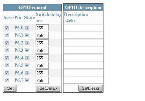
JP1 - 8 x digital outputs
JP1 is 8 bit digital output port. It can be controlled via web browser, DAEnetIP1 manager, snmp commands or via its corresponding ADC input. |
Access via Web browser
|
-
Save – Save current pin settings in the EEPROM (see switch delay)
-
Pin – Pin number
-
State – Current pin state. Checked 1, not checked - 0
-
Switch Delay – Delay in seconds for revers pin state (sec). Must be zero, before saving pin state!
-
Description – Up to 15 symbols description. After some values are changed, press corresponding button.
-
If Switch Delay is with value between 1 and 254, if the pin state was
changed then the pin will revert in the original state after defined delay.
-
If Switch Delay is set, after DAEnetIP1 bootup the pin will change his state after delay.
-
Pin with Switch Delay 0, will immediatly change its state without revert to original.
|
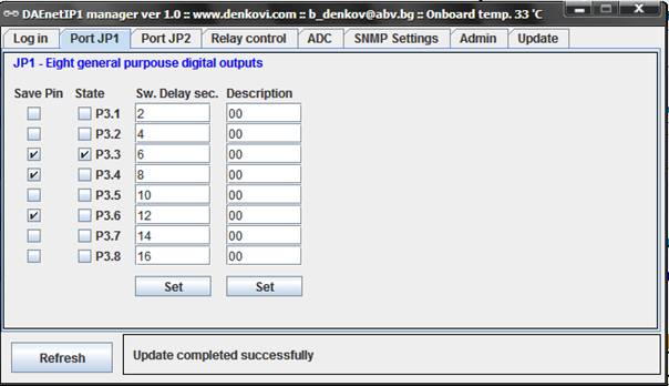
Access via DAEnetIP1 manager
|
- Save Pin– Save current pin settings in the EEPROM (see switch delay)
- State – Current pin state. Checked 1, not checked - 0
- Switch Delay – Delay in seconds for revers pin state (sec). Must be zero, Before saving pin state!
- Description – Up to 15 symbols description. After some values are changed, press “Set” button:
- If Sw. Delay sec. is with value between 1 and 254, if the pin state was changed then the pin will revert in the original state after defined delay.
- If Sw. Delay sec. is set, after DAEnetIP1 bootup the pin will change his state after delay.
- Pin with Sw. Delay sec. 0, will immediatly change his state without revert to original.
|
Access via SNMP commands
DenkoviMIB::p6lock.1 = INTEGER: High(1)
...
DenkoviMIB::p6lock.8 = INTEGER: High(1)
DenkoviMIB::p6state.1 = INTEGER: High(1)
...
DenkoviMIB::p6state.8 = INTEGER: Low(0)
DenkoviMIB::p6delay.1 = INTEGER: 1
...
DenkoviMIB::p6delay.8 = INTEGER: 8
DenkoviMIB::p6description.1 = STRING: "io 0 "
...
DenkoviMIB::p6description.8 = STRING: "io 7" |
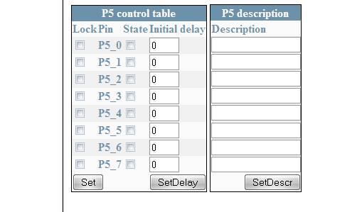
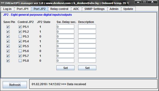
JP2 - 8 x digital inputs/outputs
JP2 is 8 bit digital input/output port. When it is ouput can be controlled via web browser, DAEnetIP1 manager, snmp commands. When it is input may be monitored via DAEnetIP1 manager and snmp commands. When there is JP2 pin level change DAEnetIP1 sends trap message to the given trap servers. |
Access via Web
|
-
Save – Save current pin settings in the EEPROM (see switch delay)
-
Pin – Pin number
-
State – Current pin state. Checked 1, not checked - 0
-
Initial Delay – Delay in seconds for revers pin state (sec). Must be zero, Before saving pin state!
-
Description – Up to 15 symbols description. After some values are changed, press corresponding button:
-
If Initial Delay is with value between 1 and 254, if the pin state was changed then the pin will revert in the original state after defined delay.
-
If Initial Delay is set, after DAEnetIP1 bootup the pin will change his state after delay.
-
Pin with Initial Delay 0, will immediatly change his state without revert to original.
|
Access via DAEnetIP1 manager
|
- Save Pin– Save current pin settings in the EEPROM (see switch delay)
- State – Current pin state. Checked 1, not checked - 0
- Switch Delay – Delay in seconds for revers pin state (sec). Must be zero, Before saving pin state!
- Description – Up to 15 symbols description. After some values are changed, press “Set” button:
- If Sw. Delay sec. is with value between 1 and 254, if the pin state was changed then the pin will revert in the original state after defined delay.
- If Sw. Delay sec. is set, after DAEnetIP1 bootup the pin will change his state after delay.
- Pin with Sw. Delay sec. 0, will immediatly change his state without revert to original.
- If you wish to use some JP2 pin as input, select the checkbox “Control JP2”. After that you can refresh the DAEnetIP1 manager and track the level of the input.
- If the state of JP2 is changed trap message will be displayed.
|
Access via SNMP commands
DenkoviMIB::JP2lock.1 = INTEGER: High(1)
...
DenkoviMIB::JP2lock.8 = INTEGER: High(1)
DenkoviMIB::JP2state.1 = INTEGER: High(1)
...
DenkoviMIB::JP2state.8 = INTEGER: Low(0)
DenkoviMIB::JP2delay.1 = INTEGER: 1
...
DenkoviMIB::JP2delay.8 = INTEGER: 8
DenkoviMIB::JP2description.1 = STRING: "io 0 "
...
DenkoviMIB::JP2description.8 = STRING: "io 7"
DenkoviMIB::JP2Value.1 = INTEGER: Low(0)
...
DenkoviMIB::JP2Value.8 = INTEGER: High(1)
Note:
JP2 can be used either digital outputs either digital inputs. The inputs visualization is implemented only over SNMP and DAEnetIP1 manager (it is not implemented via web yet). To use a JP2 pin as input its state must be set (“1”). To do this set the checkbox under label “Control JP2”.
|
JP3 - 4 x relay outputs
JP3 is 4 bit digital output port for switching relays. It can be controlled via web browser, DAEnetIP1 manager, snmp commands or via its corresponding ADC input. |
Access via Web
|
The management rules are same as JP1 digital I/O management. It is used only R0,R1,R2 and R3.
|
Access via DAEnetIP1 manager
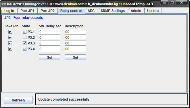
|
|
Access via SNMP commands
DenkoviMIB::RelayLock.1 = INTEGER: High(1)
...
DenkoviMIB::RelayLock.8 = INTEGER: High(1)
DenkoviMIB::RelayState.1 = INTEGER: Low(0)
.....
DenkoviMIB::RelayState.8 = INTEGER: Low(0)
DenkoviMIB::RelayDelay.1 = INTEGER: 0
....
DenkoviMIB::RelayDelay.8 = INTEGER: 0
DenkoviMIB::RelayDescription.1 = STRING: "description 1"
...
DenkoviMIB::RelayDescription.8 = STRING: "description 8"
|
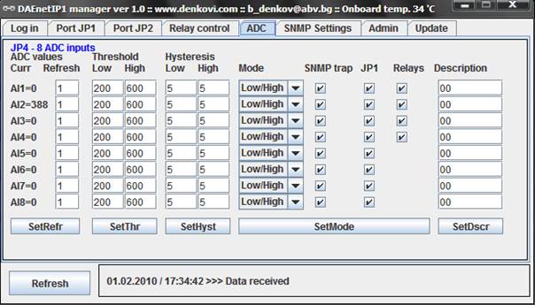
JP4 - 8 x ADC inputs
JP4 is 8 channel x 10-bit ADC input port(0 - 2.5 VDC) with 2.5VDC refferent voltage. It can be monitored via web browser, DAEnetIP1 manager, snmp commands. When some ADC input crosses given high/low threshold may be done the following: 1) a trap message may be sent. 2) JP1 pin state may be changed. 3) JP3 pin state may be changed. |
Access via Web
|
- Curr - current value measured from the channel ( 0 - 1023).
- Refresh - read frequency (1=100ms)
- Threshold (low/high) - low/high voltage limits
- Hysteresis (low/high) - voltage hysteresis
- Mode
- low - if the measured value is under LT (low threshold) the corresponding digital output ('to GPIO' - JP1 or/and 'relay') becomes 0. Over it - 1.
- high - if the measured value is over HT (high threshold) the corresponding digital output ('to GPIO' - JP1 or/and 'relay') becomes 1. Over it - 0.
- low/high - the measured value under LT corresponding digital output becomes 0. Between LT and HT - 1. Over HT - 0.
- acc - the measured value falls under LT, corresponding digital output becomes 0. Digital output becomes 1 above HT.
- SNMP trap - DAEnetIP1 sends SNMP trap message when the measured ADC value crosses given high/low threshold.
- to GPIO - Corresponding JP1 pin state is changed when the measured ADC value crosses given high/low threshold.
- relay - Corresponding relay pin state is changed when the measured ADC value crosses given high/low threshold.
- Description - channel description.
Valid values
- Refresh - from 0 to 255.
- 0 - don't read from the channel
- 10 - read every second
- 255 - don't read from the channel
- Threshold (Low/High) - from 0 to 1023
- Hysteresis (Low/High) - from 0 to 255
|
Access via DAEnetIp1 manager
|
The same conditions as the previous point.
The extra feature of DAEnetIP1 manager is that traps can be handled. When trap is received the status bar indicates this event with the following text “State changed or trap was received”
|
Access via SNMP commands
DenkoviMIB::Value.1 = INTEGER: 900
...
DenkoviMIB::Value.8 = INTEGER: 0
DenkoviMIB::SNMPRefresh.1 = INTEGER: 1
...
DenkoviMIB::SNMPRefresh.8 = INTEGER: 80
DenkoviMIB::LowThreshold.1 = INTEGER: 200
...
DenkoviMIB::LowThreshold.8 = INTEGER: 0
DenkoviMIB::HighThreshold.1 = INTEGER: 600
....
DenkoviMIB::HighThreshold.8 = INTEGER: 0
DenkoviMIB::LowHysteresis.1 = INTEGER: 5
....
DenkoviMIB::LowHysteresis.8 = INTEGER: 8
DenkoviMIB::HighHysteresis.1 = INTEGER: 5
...
DenkoviMIB::HighHysteresis.8 = INTEGER: 1
DenkoviMIB::ChannelDescription.1 = STRING: "channel 1 "
...
DenkoviMIB::ChannelDescription.8 = STRING: "channel 8 "
DenkoviMIB::Mode.1 = INTEGER: LowHigh(2)
...
DenkoviMIB::Mode.8 = INTEGER: Low(0)
DenkoviMIB::SNMPTrap.1 = INTEGER: yes(1)
...
DenkoviMIB::SNMPTrap.8 = INTEGER: no(0)
DenkoviMIB::GPIOmap.1 = INTEGER: no(0)
...
DenkoviMIB::GPIOmap.8 = INTEGER: no(0)
DenkoviMIB::RELAYmap.1 = INTEGER: yes(1)
...
DenkoviMIB::RELAYmap.8 = INTEGER: no(0) |
Useful information that may help you
- DAEnetIP1 manager - you may access the ethernet module directly via windows with user-friendly interface. This is java application so you need to have JVM installed on your PC before use DAEnetIP1 manager. The source of DAEnetIP1 manager is not free, but I am ready to give you hints by email or skype.
- DAEnetIP1 user manual (English)
- 3CServer - free TFTP server. It is necessary to run this application before update DAEnetIP1 via TFTP
- Guide how to use 3CServer with DAEnetIP1
- Netsnmp - free windows command line tool for executing SNMP commands
- Step by step guide how to install windows command line application (netsnmp) for executing SNMP commands
- The .mib file for DAEnetIP1
- The .bin file with the current actual version for DAEnetIP1
- Free powerful SNMP java library - here
- For questions, please email me: b_denkov@abv.bg
|
PAYMENT
We accept PayPal only
SHIPPING
The shipping tax is 6 USD - no matter how many DAEnetIP1 controllers you will buy. We ship via Bulgarian Post Services. We will use priority registered mail (signature is required)
QUANTITES AND DISCOUNTS
For discounts please contact with us
DELIVERY
We ship every working day. The item will be sent up to 3 working day after clear payment is received. It takes usually about 12-15 days for delivery to European countries and about 15-20 days for delivery to US, North America, South America, Africa, Asia and Australia The delivery time is determined by the posts and in some rarely cases it may be up to 30 days.
MESSAGE NOTIFICATION
Confirmation message with shipping information (including reference number) will be sent to your ebay account up to week after item is sent
Thank you for visiting our auction!