Cart is empty.
.png)
.png)


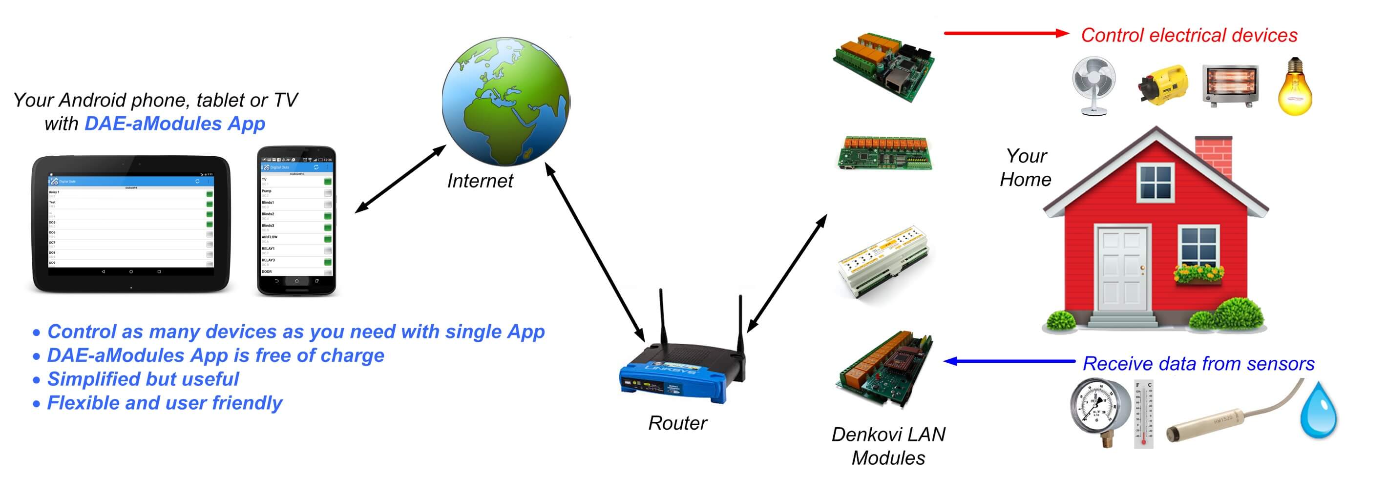
DAE-aModules is Android app for controlling all denkovi Ethernet LAN based modules. Control electrical devices, monitor sensors for temperature, humidity, light and so on. The application is developed to access all the Denkovi IP relay modules and controllers DAEnetIP2, DAEnetIP3, DAEnetIP4, smartDEN via Android phones, tablets and TVs. You can turn your mobile device into powerful automation tool in seconds. You can access relays, lights, fans, water jets or monitor sensors for temperature, humidity, pressure simply with several clicks. It can be used in fileds like home automation, industrials, sensor monitoring, remote control, data acquisition, robotics and many others.

![]()
- General overview
- List with currently supported Denkovi devices
- Current version download
- Main device list
- Add new device
- Navigation menu
- Digital inputs
- Digital outputs
- Analog inputs
- Analog outputs
- Other inputs
- Error indication
- Data transfer indication
- Device settings
- Input/output settings
- Digital inputs/outputs settings - edit values
- Analog outputs/other inputs settings - edit values
- Analog inputs - edit values
![]()
List with currently supported denkovi devices
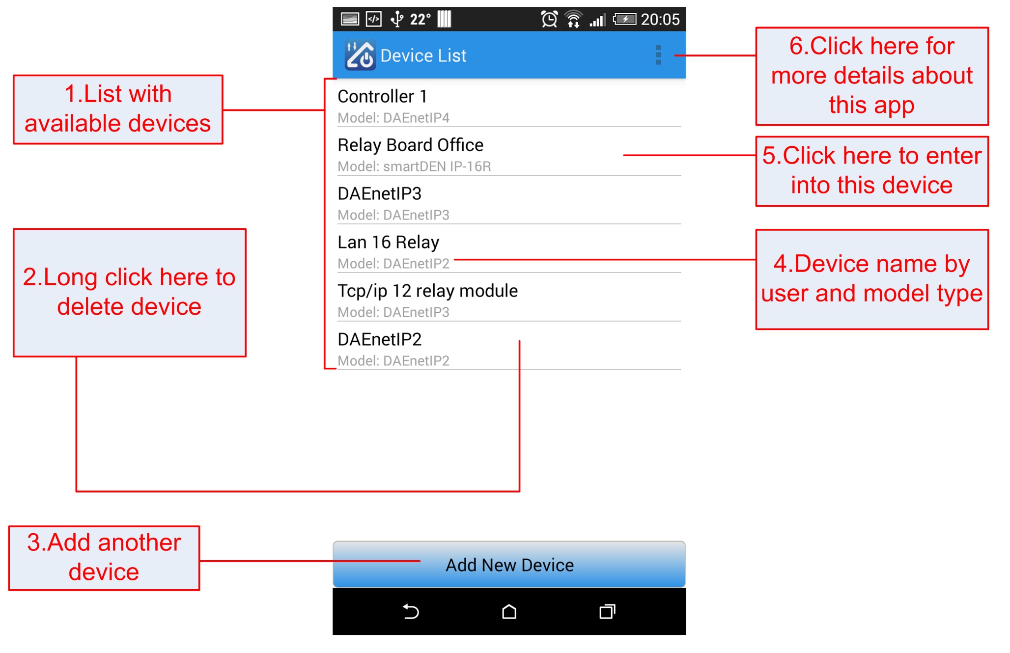
- List with all available denkovi devices - relay boards, ip controllers, i/o modules;
- Long click to delete device;
- Click this button to add new device;
- Device name and model;
- Click to enter into device;
- Click settings button for more information about this app or go to application settings.
From this activity it is possible to set up general settings for the application.
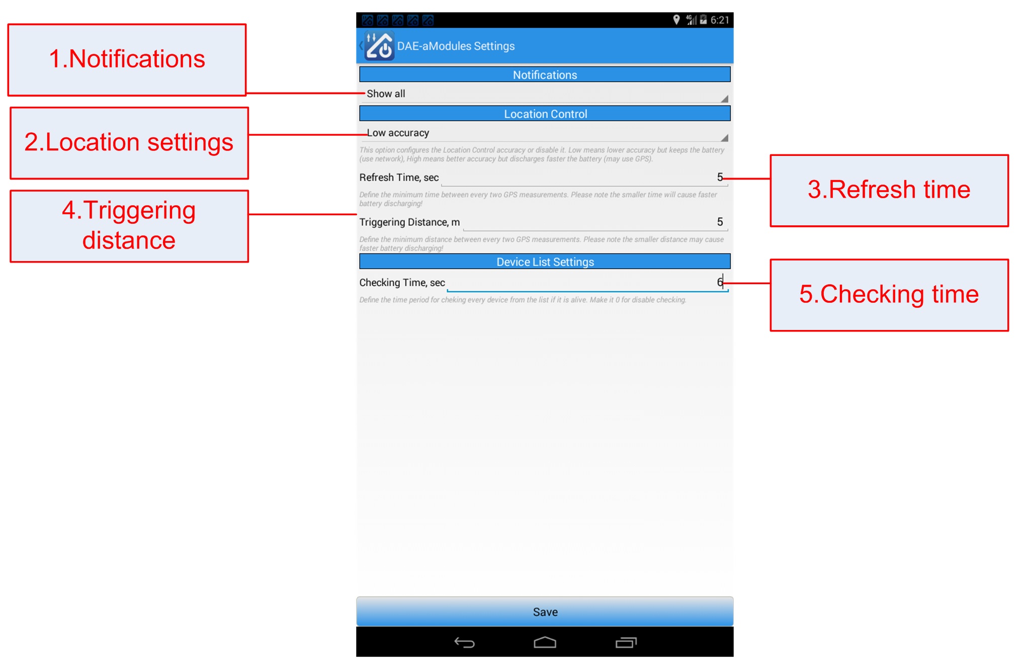
- Notifications - this adjust how often to show notifications from GPS location control events or from some device (push notifications);
- Location Control - enable or disable location control. If enabled, it can be with:
- Low Accuracy - in this mode the application may take coordinates mostly from network;
- High Accuracy - in this mode the application may take coordinates mostly from GPS;
- Refresh time - this determines the time in seconds between two GPS measurements. The smaller time, the highest battery consumption!
- Triggering distance - this determines the triggering distance in meters between two GPS measurements. The smaller distance, may highest battery consumption!
- Checking time - the refresh period in seconds for checking if device is alive or not in the main device list, 0 for disable.
If you want to add device firstly you will have to adjust its settings from the screen bellow:
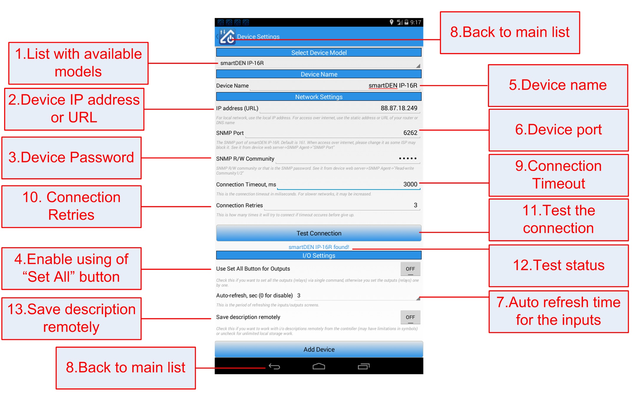
- List with all available denkovi model devices;
- Device IP address. It can be URL as well (for example www.testdevice.com);
- Device password. For some devices it is the SNMP password (for example DAEnetIP2, DAEnetIP4). For others (like DAEnetIP3) it is the HTTP (web browser) password;
- Enable / disable "Set all button". If this button is enabled, the outputs are set at once. If disabled - one by one;
- Device name;
- Network port. For some devices it is the SNMP port (for example DAEnetIP2, DAEnetIP4). For others (like DAEnetIP3) it is the HTTP (web browser) port;
- Auto-refresh period. This is the period (in seconds) for refreshing all the inputs automatically (analog, digital and other inputs). If this parameter is 0, then the auto-refresh is disabled;
- Back to the main device list;
- Connection Timeout - the time in milisecons to wait for connection to the device. For slower networks it may be increased;
- Connection Retries - how many times the app will try to connect/resend data before error appear - very useful in mobile networks;
- Tes the connection settings for this device;
- Test the connection - indicates if the network settings are OK or not;
- If this option is enabled, the app will work with i/o names directly from the remote board. This will lead to some restrictions because the names of the ports in this way are limited. If this option is disabled, the app will save/load the i/o names locally (from the phone memory) and they can be longer and with any charset.
The main navigation menu is available for every input/output screen and the settings as well. It can be shown either via 1) either via slide with figner of the left side.
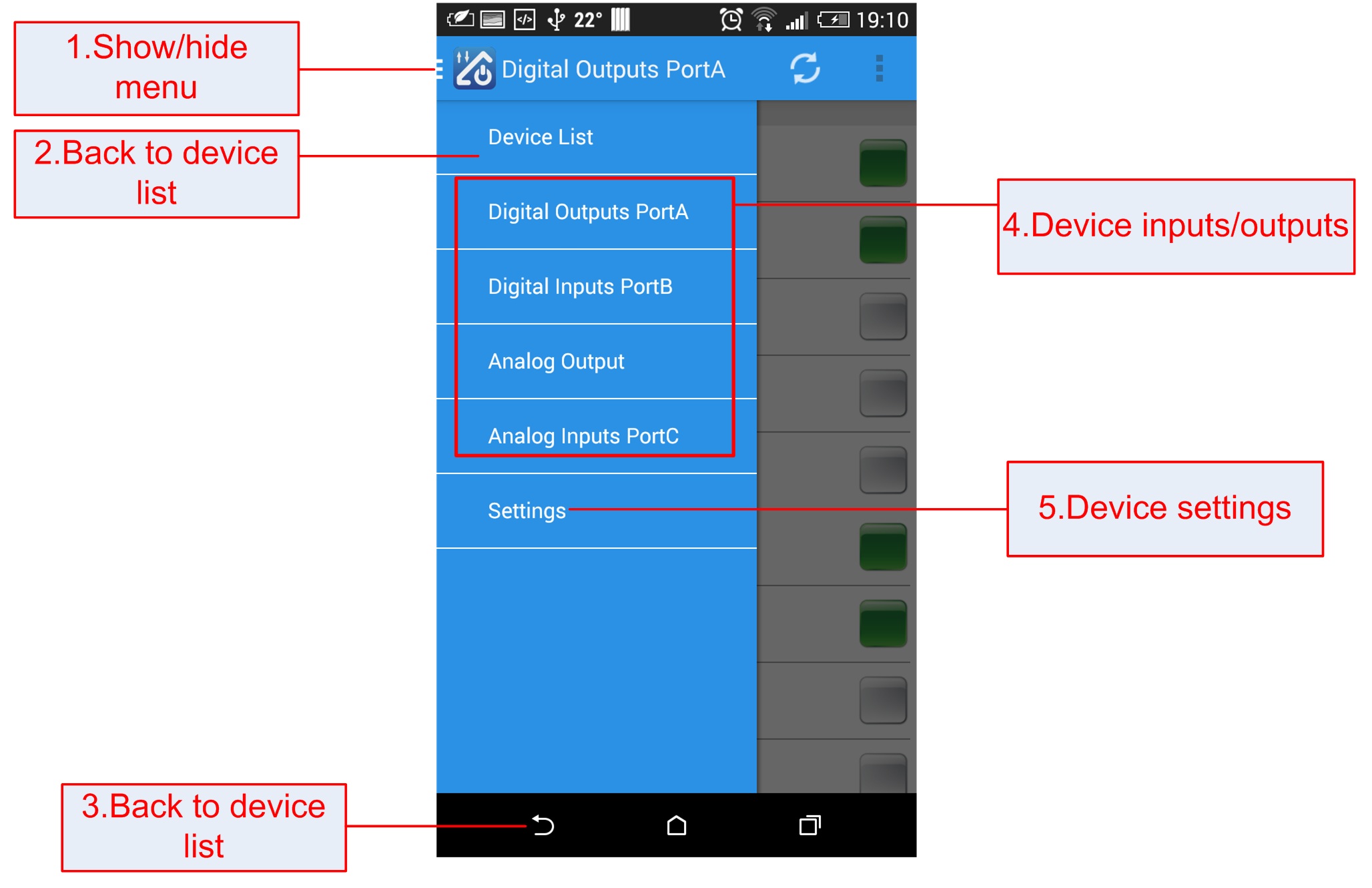
- Show/hide menu. Also slide with finger from the left side;
- Back to device list;
- Back to device list;
- Device input/outputs. Every denkovi device supports different number inputs/outpus. So this part may vary for the different devices. For example DAEnetIP4 has digital inputs, digital outputs, analog inputs and analog outputs but smartDEN IP-16R supports only digital outputs (relays);
- The settings for the particulat device.
The digital inputs serves to detect if there is voltage level at the input or on. They have 2 states - ON/OFF. Additionally some devices like DAEnetIP4 for example supports counters for the inputs which are shown as numbers before the ON/OFF state.
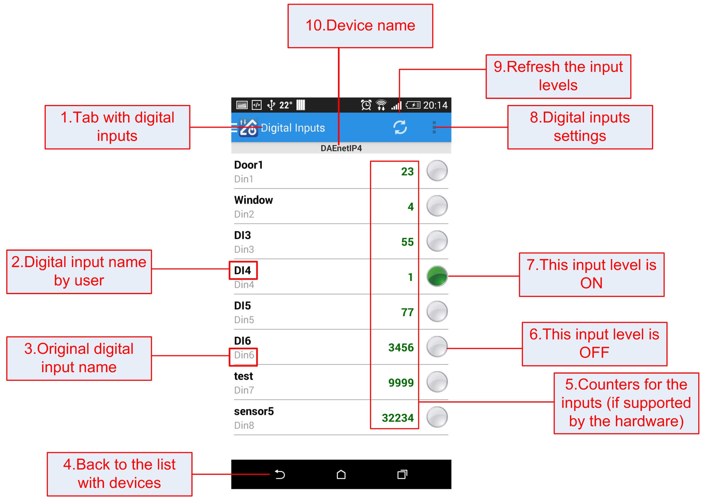
- Digital inputs;
- The name of the digital input given by the user;
- The original digital input name (read-only);
- Back to main device list;
- Counters for the digital inputs (only if suported by the hardware - for example like DAEnetIP4);
- The input level is low (OFF);
- The input level is high (ON);
- Digital inputs settings;
- Refresh the digital inputs manually;
- Current device name.
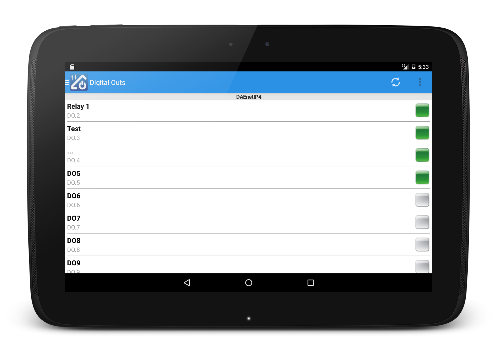
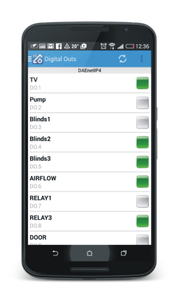
If the option "Set All" is enabled from the "Settings" section, the "Set All" button will be enabled and in this case all the states will be written with single command. Otherwise they will be set on check-box click:
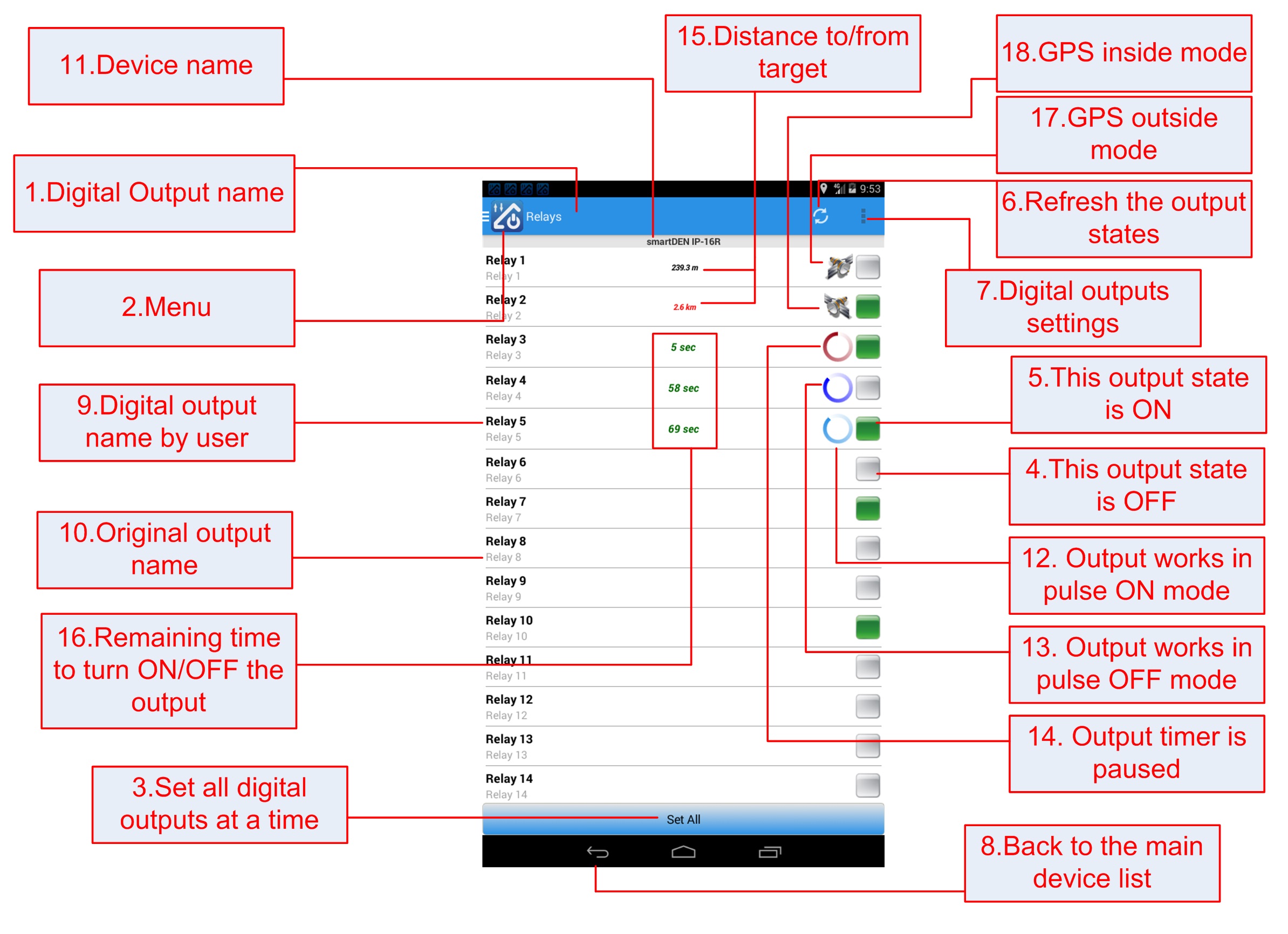
- Digital outputs;
- Menu;
- Sett all digital outputs at a time. If this button is visible this means that all the states will be set at a time otherwise one by one;
- Toggle button for controlling this digital output ON/OFF. Gray color means the output is OFF at the moment;
- Toggle button for controlling this digital output ON/OFF. Green color means the output is ON at the moment;
- Refresh digital outputs states;
- Digital output settings;
- Back to main device list;
- Name (description) for this digital output given by the user;
- Original digital output name;
- Device name;
- This output works in pulse (timer) ON mode. When it was OFF and the set to ON, it will be turned OFF again after the time elapse. Please note if the activity(screen) is closed or minimized the timer will be paused and after resuming the screen it will continue to count down. The inidicator is in light blue color;
- This output works in pulse (timer) OFF mode. When it was ON and the set to OFF, it will be turned ON again after the time elapse. Please note if the activity(screen) is closed or minimized the timer will be paused and after resuming the screen it will continue to count down. The inidicator is in darkblue color;
- Pulse (timer) is paused. If you need to pause/resume it, you may tap on this row. The inidicator is in red color;
- Indicates what is the distance to/from target as per the phone GPS coordinates:
- If selected mode is GPS_OUTSIDE:
- If this field is in black color that means it is inside the perimeter;
- If this field is in black color that means it is outside the perimeter;
- If selected mode is GPS_INSIDE:
- If this field is in black color that means it is outside the perimeter;
- If this field is in black color that means it is insude the perimeter;
- If selected mode is GPS_OUTSIDE:
- Indicates the remaining time of the timer (pulse) before set ON/OFF the output;
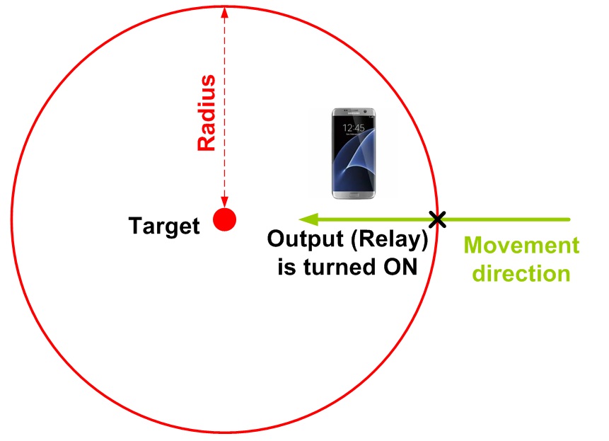
17. GPS_OUTSIDE mode: In this mode the output (relay) will be set ON when the user crosses the set radius leaving the perimeter. This is suitable for example when the user leaves his work place and going home an electrical device must be switched ON automatically. Please note an internet connection is required for this command otherwise it won't be executed.

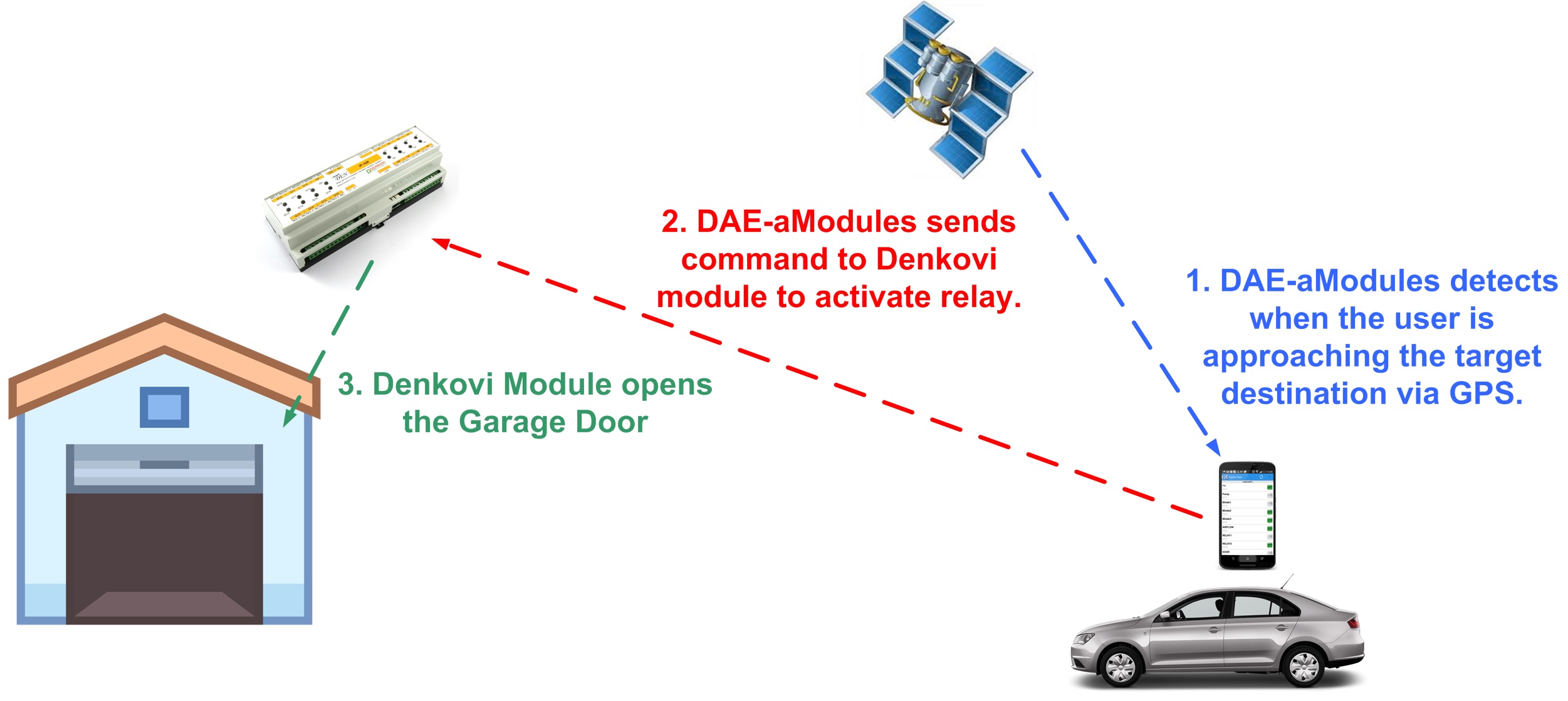
18. GPS_INSIDE mode: In this mode the output (relay) will be set ON when the user crosses the set radius entering the perimeter. This is suitable for example when the user approach his house and want to open some garage door automatically. Please note an internet connection is required for this command otherwise it won't be executed.
Please note in order to work with the GPS location functions:
- The phone location must be enabled;
- The permisions for the app must be granted;
Analog inputs values can be scaled and in this way they are shown in real units like Deg C, Deg F, Volts, Amperes and so on. Please note the scaling is done on software level (level Android) and it is not done in the hardware side:
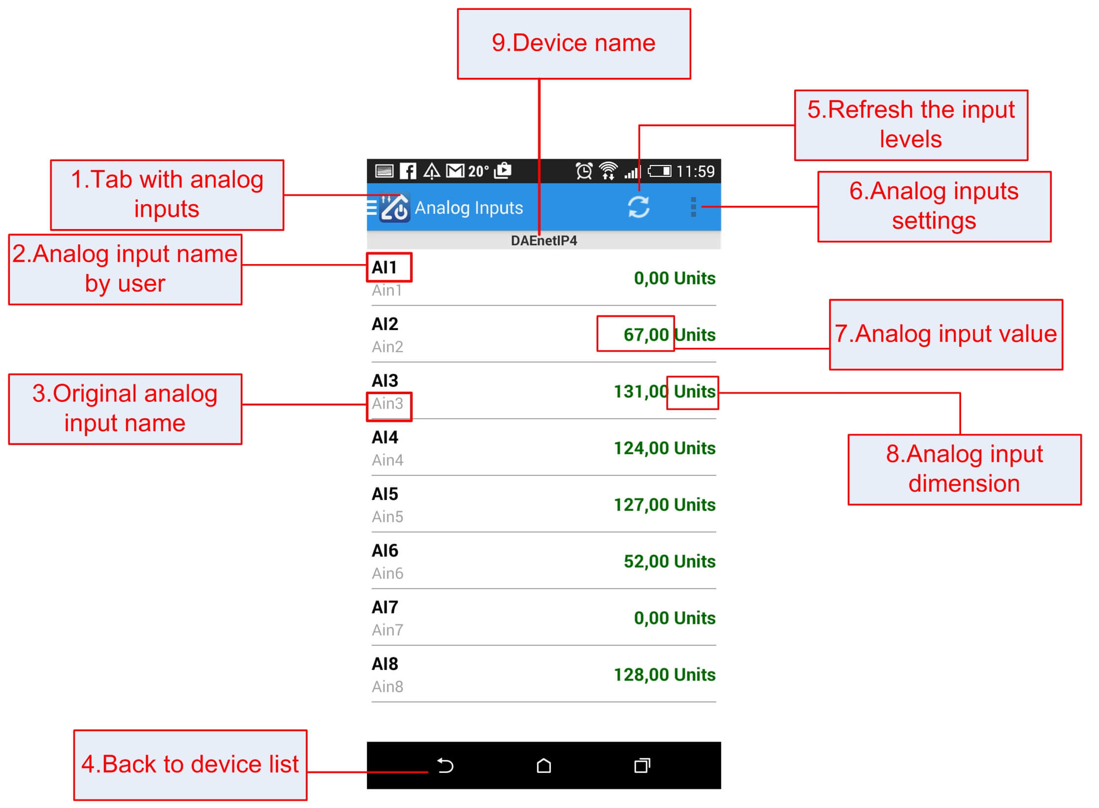
- Analog inputs;
- Analog input name by user;
- Original analog input name;
- Back to the main device list;
- Refresh the analog inputs levels manually;
- Analog inputs settings;
- Analog input value;
- Analog input dimension;
- Device name;
These outputs are suitable for dimming lights for example:
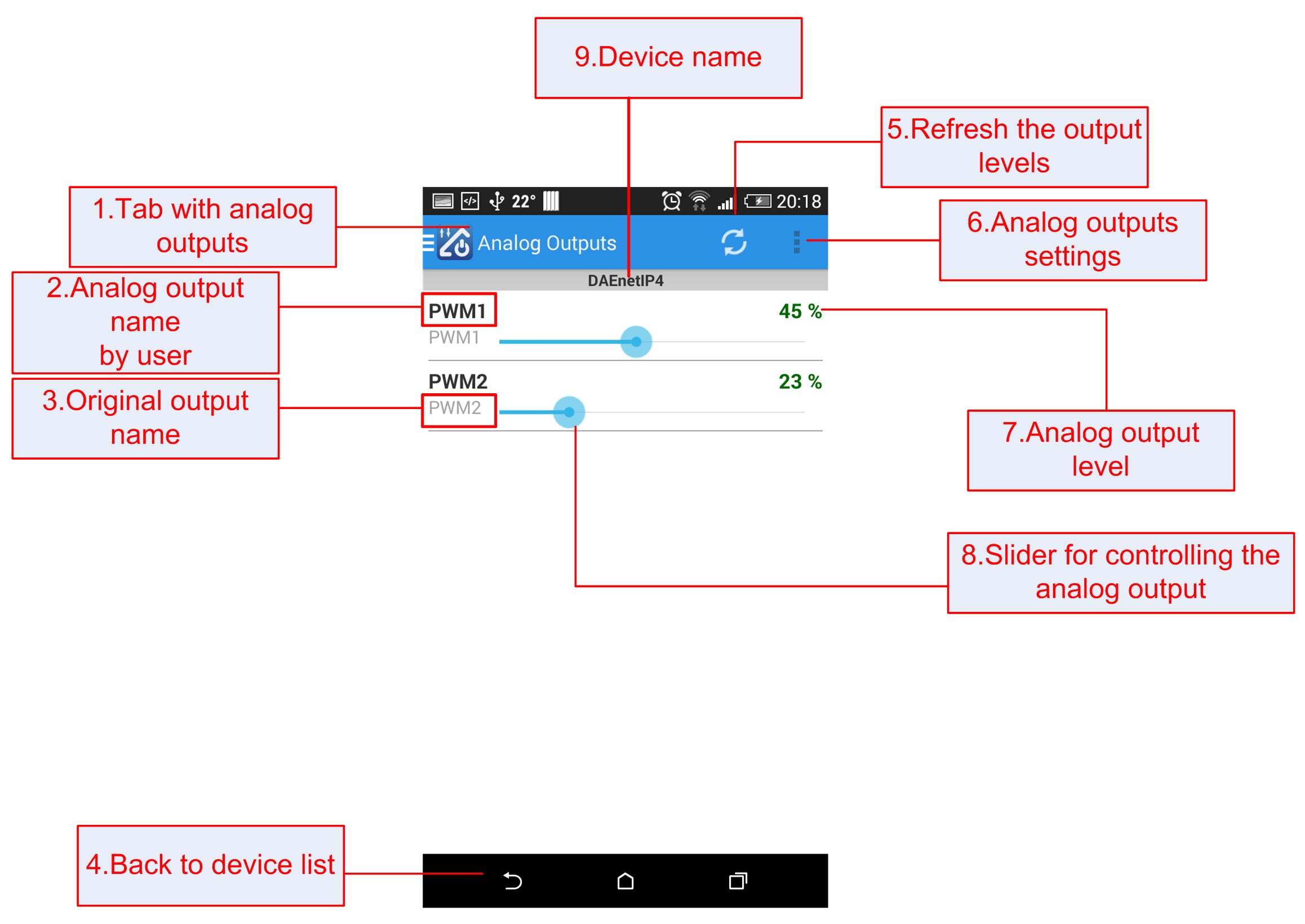
- Analog outputs;
- Analog output name by user;
- Original output name;
- Back to main device list;
- Refresh the output levels;
- Settings;
- Analog output level;
- Slider for controlling the analog output;
- Device name.
This screen displays values from special inputs supported by some of our devices designed to measure temperature, humidity, pressure:
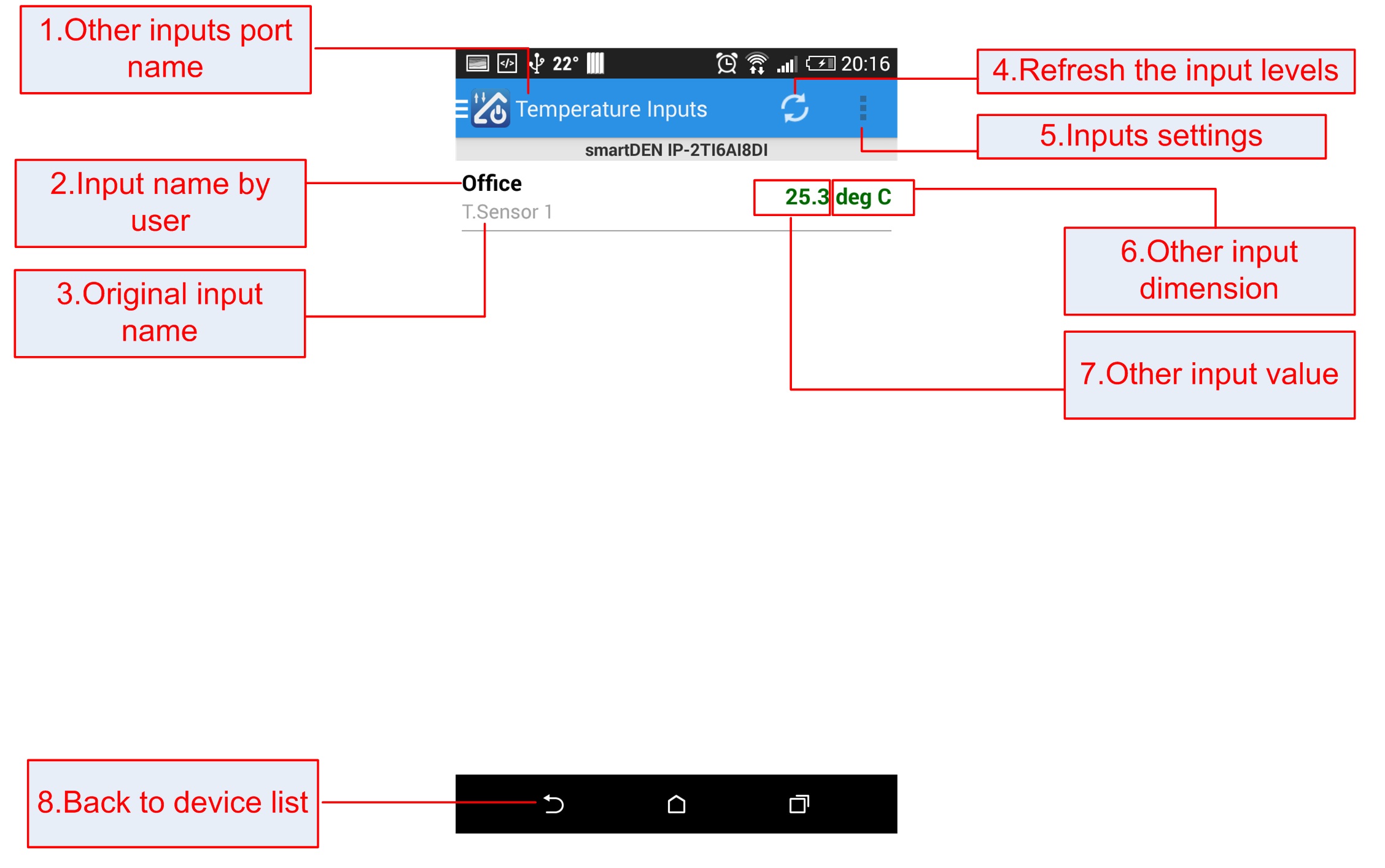
- Other inputs;
- Input name by user;
- Original input name;
- Refresh the inputs manually;
- Settings;
- Inputs dimension (units);
- Input value;
- Back to the main device list.
This message is shown for 2 seconds in case there is not access to the denkovi device or the phone is not connected to the Internet.
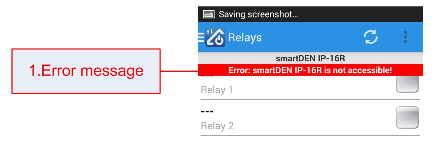
- Error message (red color).
Usually this indication is shown during sending requests to the denkovi device. While the refresh indicator is spinning this also means there is data transfer.
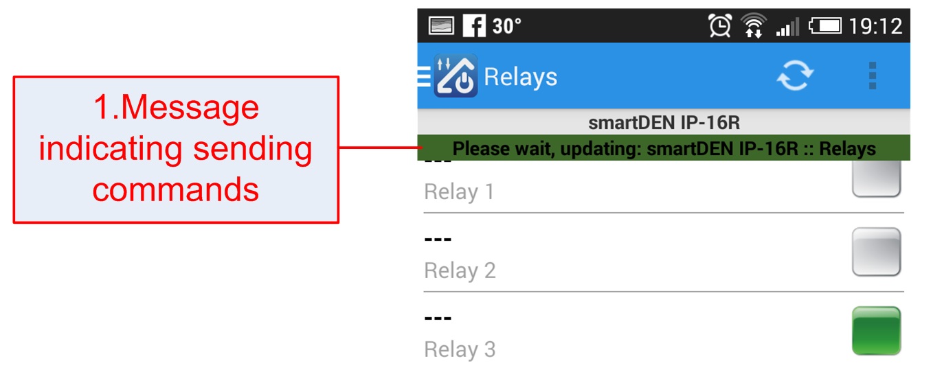
- Data transfer indication (green color).
These settings screen can be invoked from the navigation menu for the current selected denkovi device.

- Device name;
- Device IP address. It can be URL as well (for example www.testdevice.com);
- Device password. For some devices it is the SNMP password (for example DAEnetIP2, DAEnetIP4). For others (like DAEnetIP3) it is the HTTP (web browser) password;
- Enable / disable "Set all button". If this button is enabled, the outputs are set at once. If disabled - one by one;
- Network port. For some devices it is the SNMP port (for example DAEnetIP2, DAEnetIP4). For others (like DAEnetIP3) it is the HTTP (web browser) port;
- Auto-refresh period. This is the period (in seconds) for refreshing all the inputs automatically (analog, digital and other inputs). If this parameter is 0, then the auto-refresh is disabled
- Connection Timeout - the time in milisecons to wait for connection to the device. For slower networks it may be increased;
- Connection Retries - how many times the app will try to connect/resend data before error appear - very useful in mobile networks;
- Test the connection settings for this device;
- Test status - indicates if the network settings are OK or not.
From this screen you can see what is the name for each input/output. It can be invoked from every input/output screen settings button.
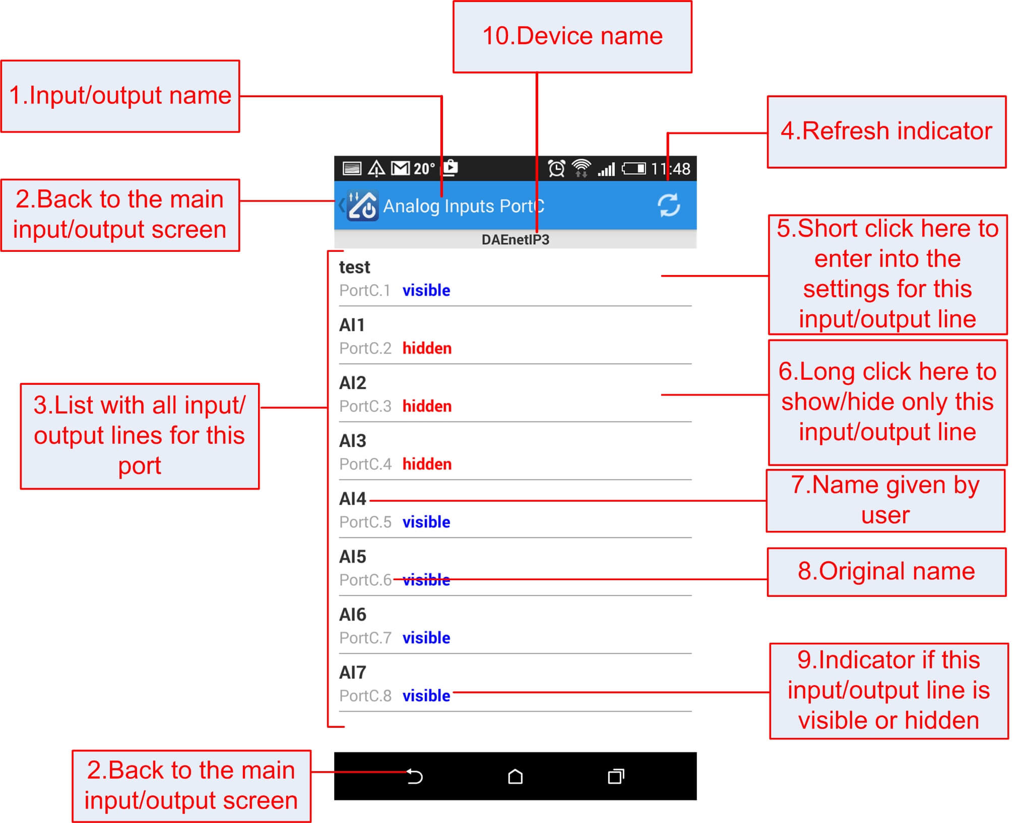
- Input/output name;
- Back to the main input/output screen;
- List with all input/output lines for this port;
- Refresh indicator - refresh the i/o lines;
- Short click to enter into this i/o settings dialog;
- Loong click to switch visible/hidden this i/o line;
- I/O line name by the user;
- Original name for this i/o line;
- Indicator if this i/o is visible or not;
- Device name.
Digital output settings - edit values
From this screen you can set the name (description) of every digital output and show/hide it and also to set the working mode.
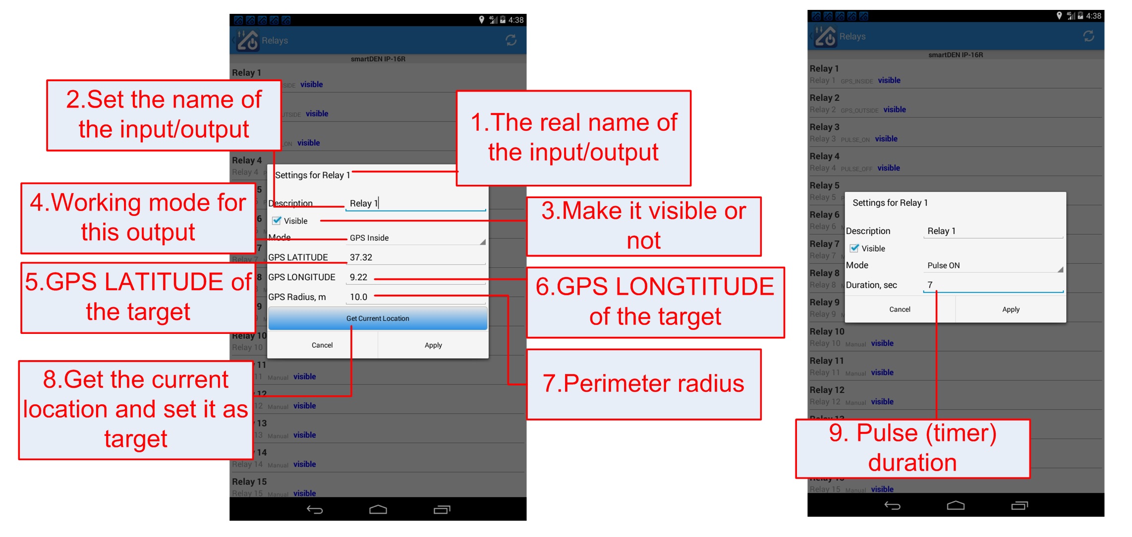
- Digital output original name;
- Set the name of this output;
- Make it visible or not;
- The working mode for this output;
- The GPS Latitude of the target;
- The GPS Longtitude of the target;
- The perimeter radius;
- Get the current location of the phone and set it to the target. Please note if location is turned for first time it may takes several seconds (a minitue sometimes) to retrieve the coordinates!
Digital input settings - edit values
From this screen you can set the name (description) of every digital input and show/hide it.
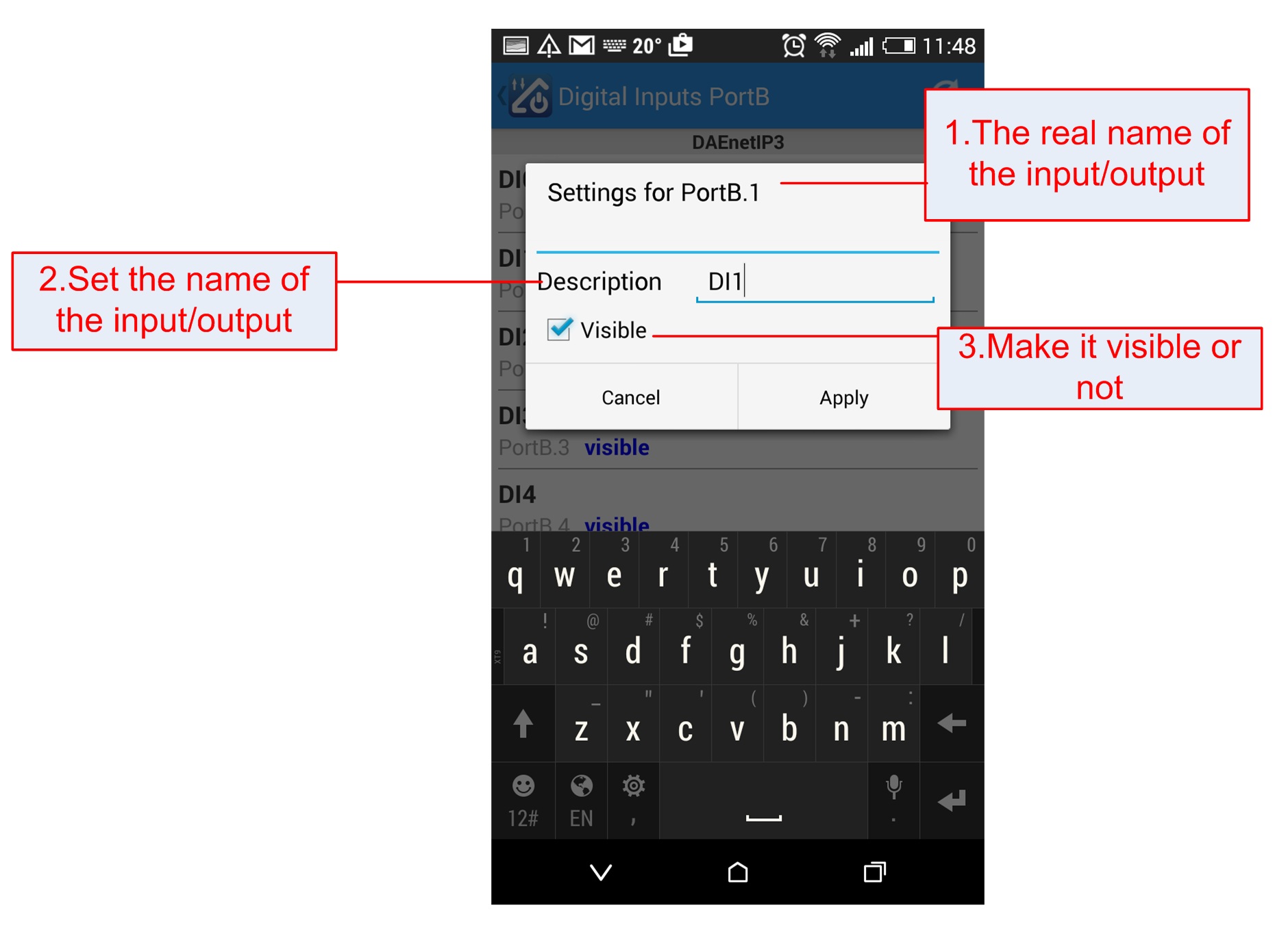
- Input original name;
- Set the name of this input;
- Make it visible or not.
Analog output/other inputs settings - edit values
From this screen you can set the name (description) of every analog output/other input and show/hide it.
- Input/output original name;
- Set the name of this input/output;
- The units for this input/output;
- Make it visible or not.
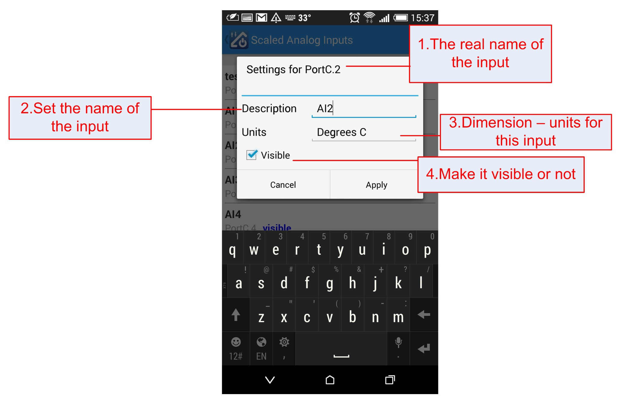
Analog inputs settings - edit values
From this screen you can set the name (description) of every analog input and show/hide it. Here you can scale every analog input as well. You can set the value at 0, the value at maximum (1024 usually) and units (for example Volts, Meters, KG...). More about scaling - here:
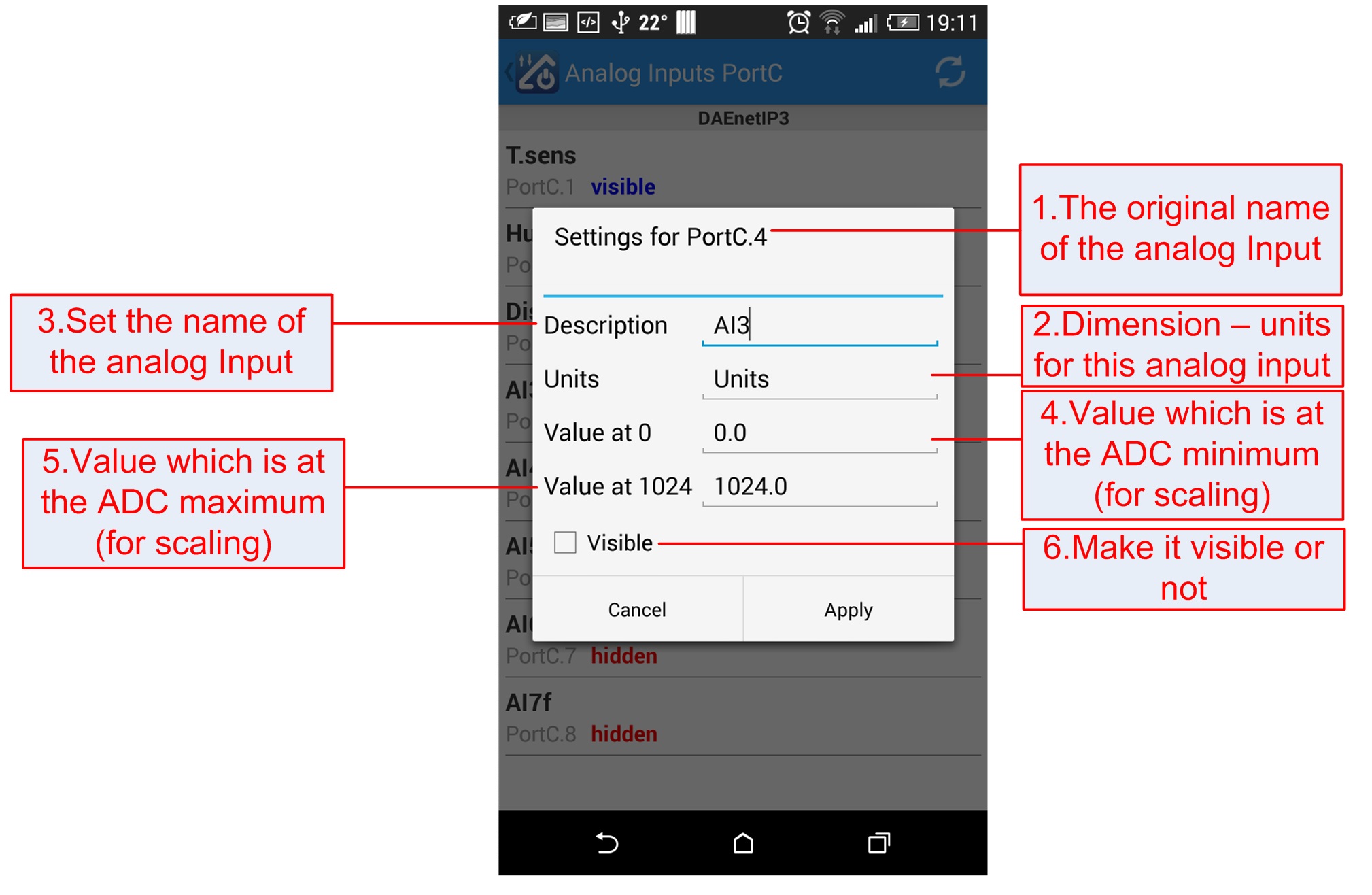
- Input/output original name;
- The units for this analog input;
- Set the name of this analog input;
- Value at 0;
- Value at maximum (1024 usually);
- Make it visible or not.
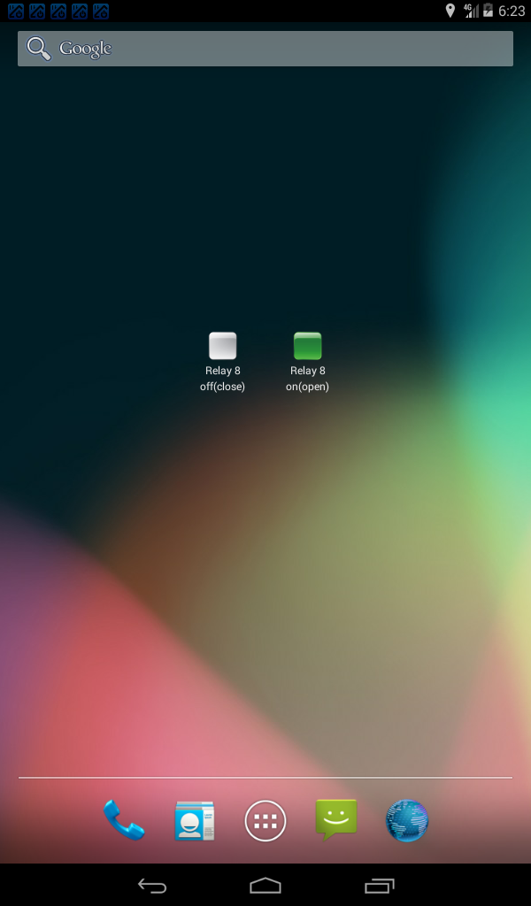
From version 1.2 it is possible to control digital outputs (relays) via widgets. Please it is possible to do only ON/OFF (no timers)!
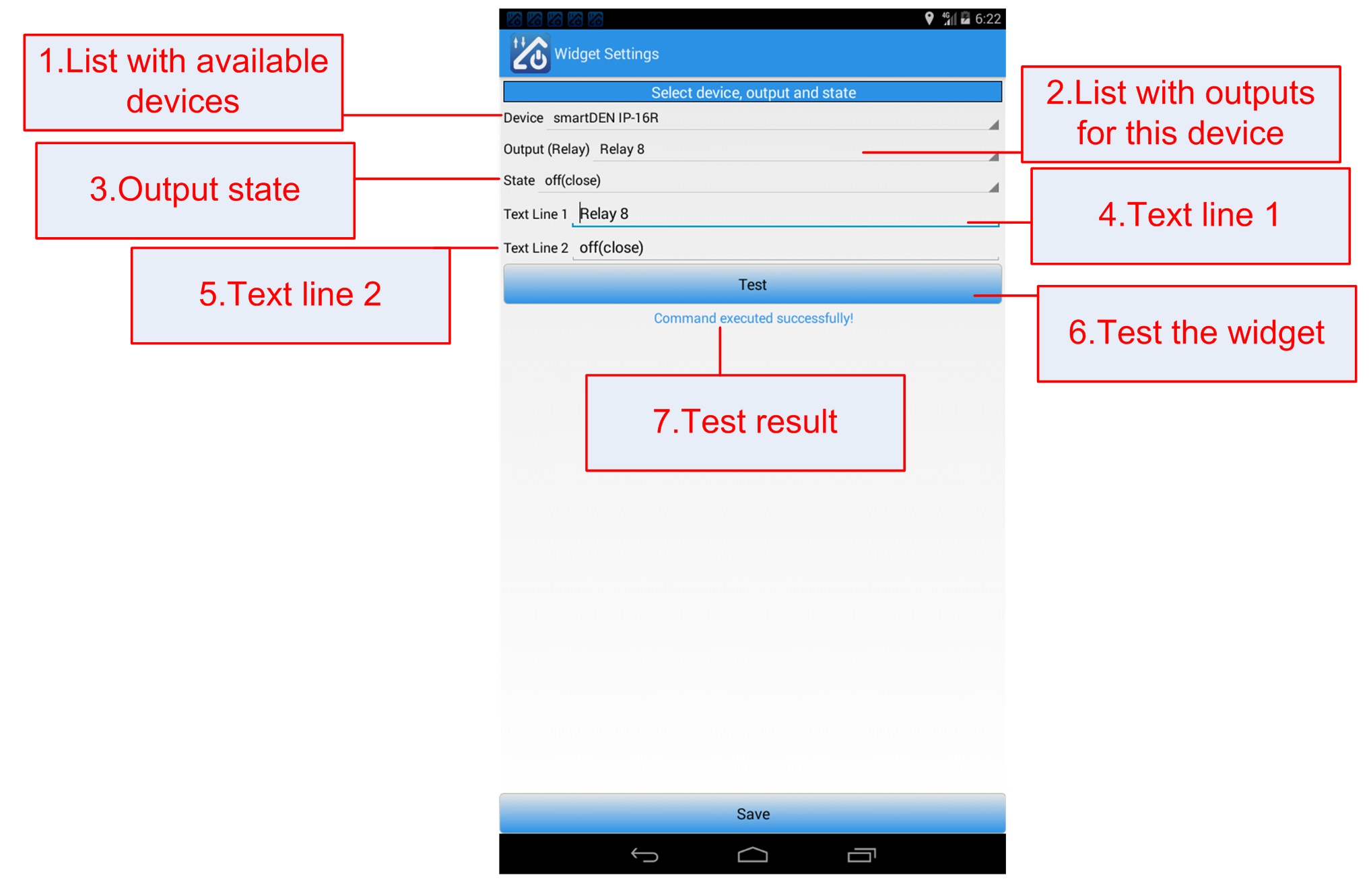
- List with available devices. Please note only devices supporting outputs will be valid for widgets;
- The digital outputs for this device;
- Output state - on or off;
- Text line 1 - the widget top line text;
- Text line 2 - the widget bottom line text;
- Test the widget - test the widget action;
- Test result - indicator showing if the test was ok or not.


